Mulch recycling machine
A recycling machine and mulch technology, which is applied to collectors, agricultural machinery and implements, applications, etc., can solve the problems of low work efficiency and inability to dig out mulch fragments, and achieve the effect of simple structure, high picking efficiency and good recycling effect
- Summary
- Abstract
- Description
- Claims
- Application Information
AI Technical Summary
Problems solved by technology
Method used
Image
Examples
Embodiment 1
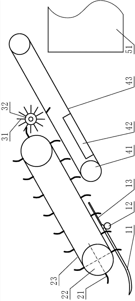
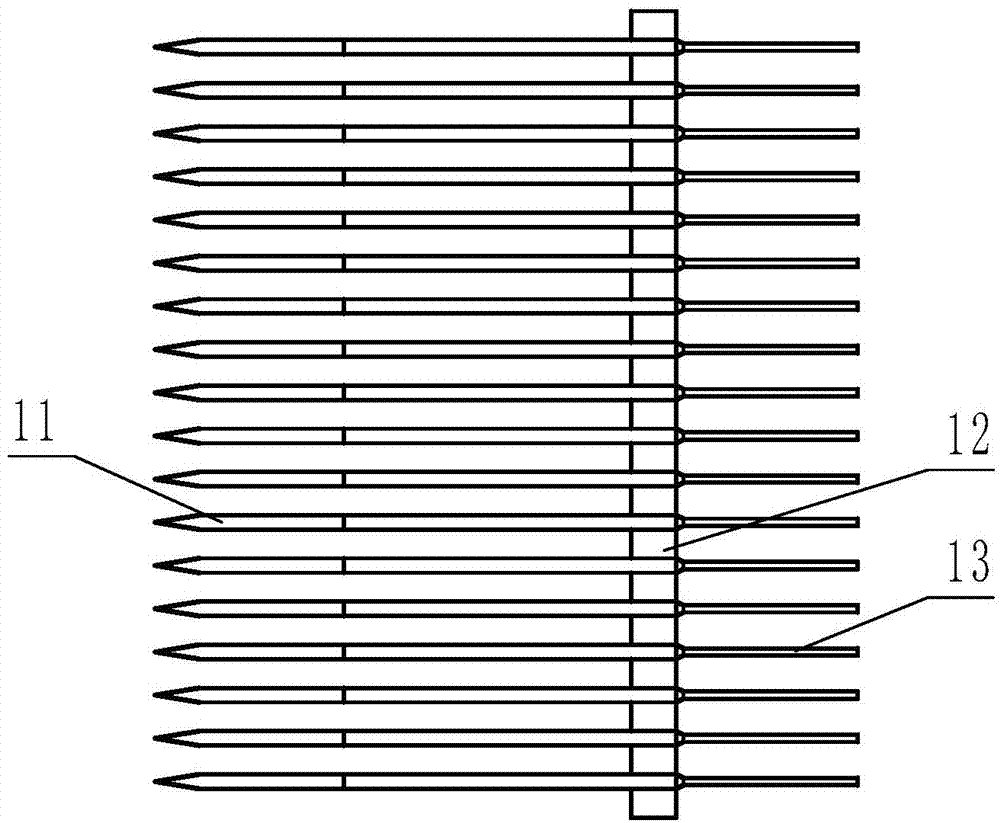
[0041] Example 1: refer to Figure 1~5 , is a structural schematic diagram of Embodiment 1 of the present invention, including a suspension frame, a main frame and a transmission mechanism, and a tooth (11) is arranged on the lower part of the main frame, and the tooth (11) is a row of rod-shaped objects passing through a connecting rod A (12) is connected to form a comb-shaped body. The rear end of the tooth (11) is provided with a tail rod (13). The tail rod (13) is located at the rear of the connecting rod A (12). Teeth (11) are thinner.
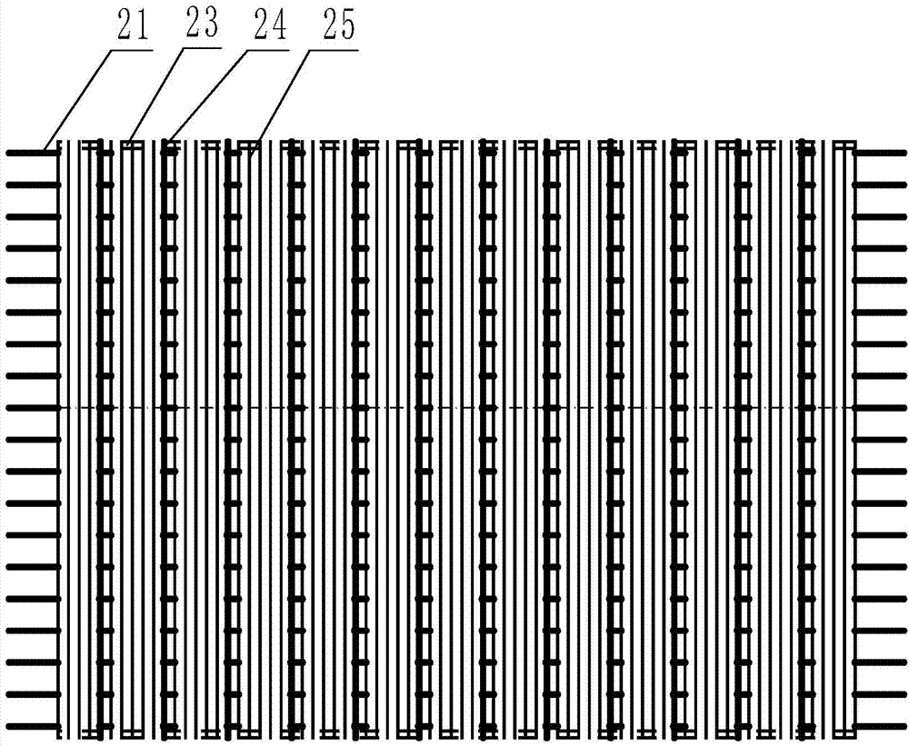
[0042] The upper part of the tooth (11) is provided with a pick-up device, which includes a set of drive wheels (22) and a chain (23) arranged on the set of drive wheels (22). The chain (23) is provided with rows of Cross bar (24), the cross bar (24) is provided with the pick-up tooth (21) of row, the pick-up tooth (21) on the cross bar (24) of row forms pick-up tooth (21) display, simultaneously, with chain (23) and cross bar (24) ar...
Embodiment 2
[0046] Example 2: refer to Image 6 and 7 , is a schematic structural diagram of Embodiment 2 of the present invention. Compared with Embodiment 1, the difference of this embodiment is that the wall of the driving drum (41) is mesh-shaped, and the inner wall of the drum (41) is provided with a spiral conveying Page board (46), if the soil and sundries stuck on the conveyor belt cannot be scraped off by the "herringbone" scraper 42, it can enter the drum (41) from the mesh 47 and pass through the inner wall of the drum (41) The rotation of the spiral conveying leaf plate (46) is removed, which can further improve the removal effect.
Embodiment 3
[0047] Example 3: refer to Figure 8 , is a schematic structural diagram of Embodiment 3 of the present invention. Compared with Embodiment 1, the difference of this embodiment is that the connecting rod A (12) is a rotatable shaft and is provided with a pendulum mechanism, and the pendulum The vibrating mechanism includes a rocker (14), a pull rod (15) and a crank wheel A (16). One end of the rocker (14) is fixedly connected with the connecting rod A (12) horizontally, and the other end is hinged with the pull rod (15). The pull rod (15) ) is eccentrically hinged with the crank wheel A (16) to form a rocker mechanism, so that the pull rod (15) pulls the rocker (14) to swing with the connecting rod A (12) as the axis, and then the tooth (11) The connecting rod A (12) is a shaft swing, which can better excavate the residual plastic film buried in the ground and shake off the soil.
PUM
 Abstract
Description
Claims
Application Information
 - Generate Ideas
- Intellectual Property
- Life Sciences
- Materials
- Tech Scout
- Unparalleled Data Quality
- Higher Quality Content
- 60% Fewer Hallucinations
Browse by: Latest US Patents, China's latest patents, Technical Efficacy Thesaurus, Application Domain, Technology Topic, Popular Technical Reports.
© 2025 PatSnap. All rights reserved.Legal|Privacy policy|Modern Slavery Act Transparency Statement|Sitemap|About US| Contact US: help@patsnap.com


