
A wireless charging device and method

A wireless charging device and wireless charging technology, applied in the direction of current collectors, electric vehicles, electrical components, etc., can solve problems such as not intersecting with the receiving coil, uncertain magnetic field direction of the transmitting coil, and large power loss

Active Publication Date: 2017-04-19
LENOVO (BEIJING) LTD
View PDF4 Cites 0 Cited by
  • Summary
  • Abstract
  • Description
  • Claims
  • Application Information

AI Technical Summary

Problems solved by technology

[0006] In view of this, the purpose of the present invention is to provide a wireless charging device and method, which can adjust the radiation angle of the induced electromagnetic field generated in the wireless charging coil, so as to solve the problem of uncertain magnetic field direction of the transmitter coil in the prior art. As a result, it is easy for the magnetic field lines excited by the transmitter coil to not intersect with the receiver coil, resulting in a problem of large power loss

Method used


Image

  • A wireless charging device and method
  • A wireless charging device and method
  • A wireless charging device and method

Examples


Embodiment Construction

[0047] In order to make the purpose, technical solutions and advantages of the embodiments of the present invention clearer, the technical solutions in the embodiments of the present invention will be clearly and completely described below in conjunction with the drawings in the embodiments of the present invention. Obviously, the described embodiments It is a part of embodiments of the present invention, but not all embodiments. Based on the embodiments of the present invention, all other embodiments obtained by persons of ordinary skill in the art without making creative efforts belong to the protection scope of the present invention.

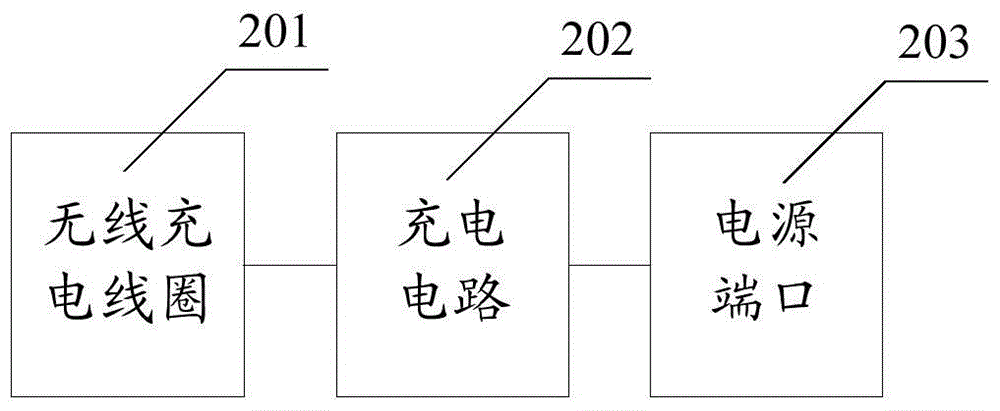
[0048] Such as figure 2As shown, it is a schematic structural diagram of Embodiment 1 of a wireless charging device provided in this application. The wireless charging device is applied to the transmitting end of the wireless charging system. The wireless charging device includes: a wireless charging coil 201, a charging circuit 202 and a po...


PUM


Abstract

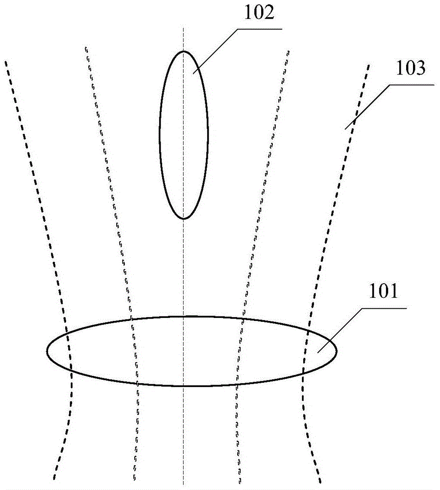
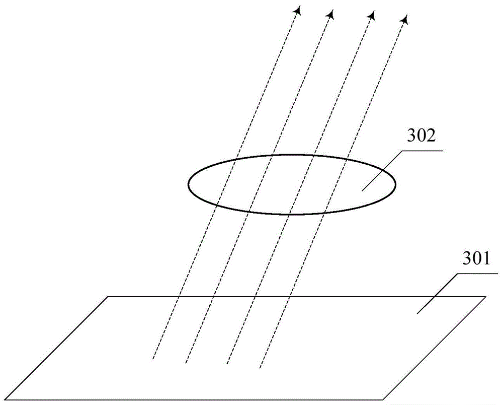
The invention provides wireless charging equipment applied to a transmitting terminal. The wireless charging equipment comprises a wireless charging coil, a charging circuit connected with the wireless charging coil, and a power port connected with the wireless charging circuit. The included angle between the direction of a magnetic field line in a magnetic field excited by the wireless charging coil in the electrifying process and the plane where the wireless charging coil is located is larger than 0 degree and smaller than 90 degrees, in other words, the magnetic field line is neither perpendicular to the plane where the wireless charging coil is located nor parallel to the plane where the wireless charging coil is located, the direction of the magnetic field line is oblique, and therefore no matter whether the wireless charging coil of a receiving terminal used in cooperation with the transmitting terminal is in a perpendicular mode or a paralleled mode, the wireless charging coil of the receiving terminal can intersect with the magnetic field line in the magnetic field excited by the wireless charging coil of the transmitting terminal to form an energy transmission channel. Accordingly, the transmitting terminal can charge the receiving terminal, electric energy loss can be reduced, and charging efficiency can be improved.

Description

technical field [0001] The invention belongs to the field of wireless charging, and in particular relates to a wireless charging device and method. Background technique [0002] Wireless charging technology (Wireless Charging Technology) is a kind of wireless power transmission technology, using near-field induction, the power supply equipment transmits energy to the power-consuming device, the device uses the received energy to charge the battery, and at the same time for its for its own operation. [0003] Commonly used wireless charging methods in the prior art mainly include inductive and resonance methods. However, no matter which solution is adopted, it relies on the magnetic field excited by the coil at the transmitting end (power supply device) to act on the coil at the receiving end (device to be charged) to form an energy transmission channel so that the transmitting end can charge the receiving end. [0004] However, the magnetic field formed by the existing des...

Claims


Application Information

Patent Timeline
Patent Type & Authority Patents(China)
IPC IPC(8): H02J50/10H02J7/00
CPCH02J7/025
Inventor 张传雨
Owner LENOVO (BEIJING) LTD
Learn More