
Spring clutch

A technology of spring clutches and clutches, applied in the direction of clutches, friction clutches, mechanically driven clutches, etc., which can solve problems such as inconvenient operation and complex structure

Inactive Publication Date: 2015-01-28
芜湖市中亚汽车制动元件有限公司
View PDF6 Cites 2 Cited by
  • Summary
  • Abstract
  • Description
  • Claims
  • Application Information

AI Technical Summary

Problems solved by technology

This separation and joining method is complex in structure and inconvenient to operate

Method used


Image

  • Spring clutch

Examples


Embodiment Construction

[0018] Specific embodiments of the present invention will be described in detail below in conjunction with the accompanying drawings. It should be understood that the specific embodiments described here are only used to illustrate and explain the present invention, and are not intended to limit the present invention.

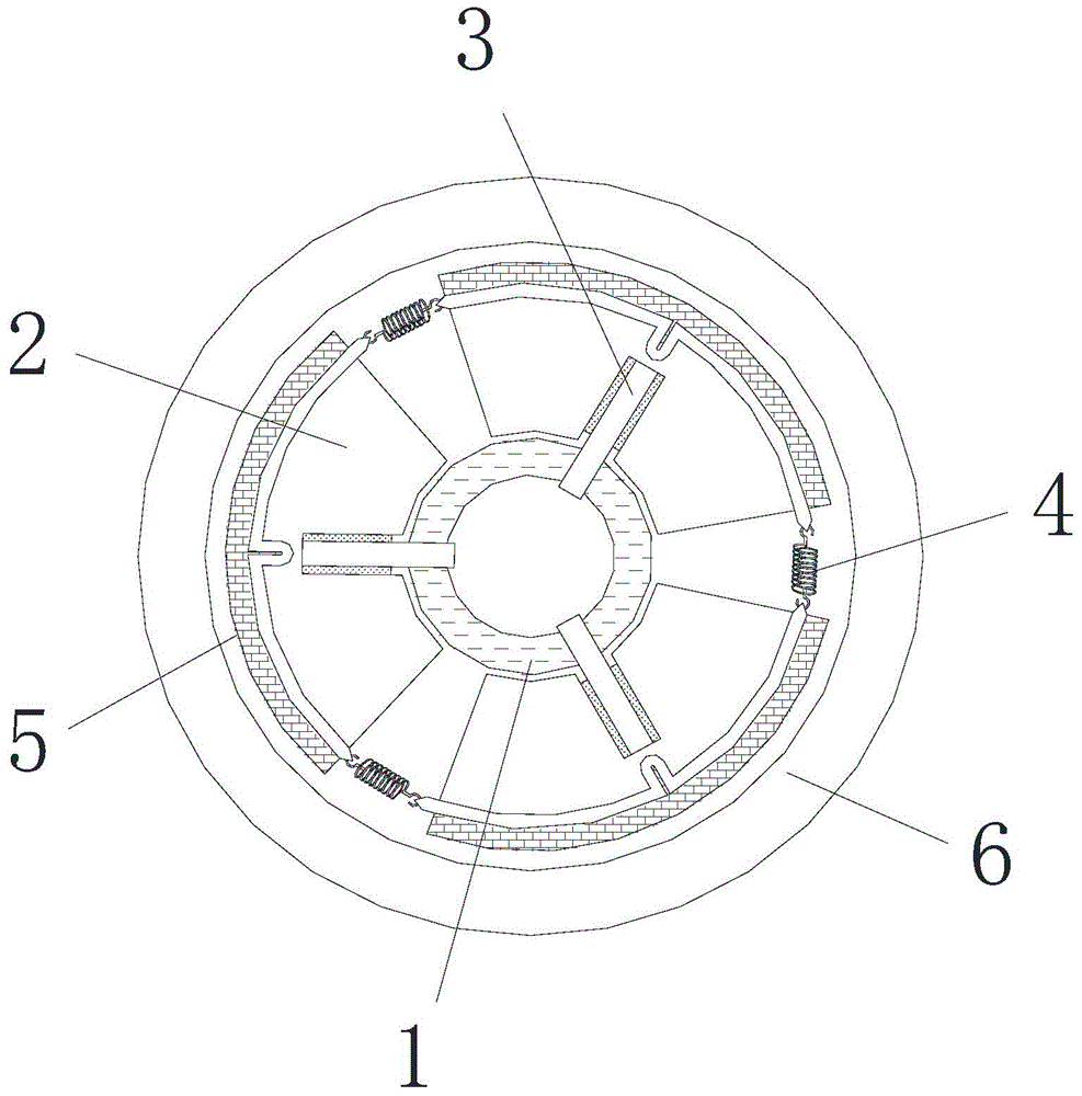
[0019] see figure 1 , the present invention provides a spring clutch, the spring clutch includes a hub 1, a clutch cover 6, a fan-shaped flywheel 2, a guide post 3, an elastic connector 4 and a fan-shaped friction plate 5; and the fan-shaped flywheel 2, the guide The number of columns 3, elastic connectors 4 and the sector-shaped friction plates 5 are all three; the hub 1 is coaxially arranged in the clutch cover 6; the three guide columns 3 are spaced apart from each other in the circumferential direction are connected to the outer peripheral portion of the hub 1 and extend radially outward respectively; the three sector flywheels 2 correspond to the three gui...


PUM


Abstract

The invention discloses a spring clutch. The spring clutch comprises a hub (1), a clutch hood (6), three fan-shaped flywheels (2), three guide columns (3), three elastic connecting pieces (4) and three fan-shaped friction sheets (5), wherein the hub is coaxially arranged in the clutch hood; the guide columns are connected to the peripheral part of the hub at intervals along the circumferential direction and extend outwards along the radial direction; the fan-shaped flywheels correspond to the guide columns; a radial guide groove matched with each guide column is formed inside the corresponding fan-shaped flywheel; each fan-shaped flywheel is mounted on the corresponding guide column through the corresponding radial guide groove in a sleeving manner and can radially move; the fan-shaped friction sheets correspond to the fan-shaped flywheels and are arranged between the fan-shaped flywheels and the clutch hood; each fan-shaped friction sheet is combined with the corresponding fan-shaped flywheel into a whole; any two adjacent fan-shaped friction sheets are elastically connected through the corresponding elastic connecting piece. The spring clutch is simple in structure and convenient to disengage and engage.

Description

technical field [0001] The invention relates to a spring clutch. Background technique [0002] Friction clutch is the most widely used and oldest type of clutch. It is basically composed of four parts: the active part, the driven part, the pressing mechanism and the operating mechanism. The main and driven parts and the pressing mechanism are the basic structures to ensure that the clutch is in the engaged state and can transmit power, while the clutch operating mechanism is mainly a device for disengaging the clutch. During the separation process, step on the clutch pedal, first eliminate the free gap of the clutch in the free stroke, and then generate a separation gap in the working stroke, and the clutch is separated. During the engagement process, the clutch pedal is gradually released, and the pressure plate moves forward under the action of the compression spring, first to eliminate the separation gap, and to exert sufficient compression force on the pressure plate, d...

Claims


Application Information

Patent Timeline
Patent Type & Authority Applications(China)
IPC IPC(8): F16D13/16
Inventor 董家保苏堤董家兵
Owner 芜湖市中亚汽车制动元件有限公司
Learn More