
Automatic welding device and welding process thereof

An automatic welding and welding torch technology, applied in welding equipment, auxiliary devices, welding equipment and other directions, can solve the problems of low degree of automation, welding quality, work efficiency and safety of personnel, insufficient energy saving and environmental protection, poor versatility, etc., to improve welding production. Efficiency, a wide range of welding applications, and the effect of easy manufacturing

Active Publication Date: 2015-01-28
芜湖胜帮机电设备有限公司
View PDF8 Cites 4 Cited by
  • Summary
  • Abstract
  • Description
  • Claims
  • Application Information

AI Technical Summary

Problems solved by technology

[0002] At present, compared with other types of metal forming processing, welding processing is not highly automated and relies more on manual operations. There are deficiencies in welding quality, work efficiency, personnel safety, energy saving and environmental protection. Although the welding robot industry has developed in recent years Rapid, powerful welding robot, but its price is expensive, unaffordable by ordinary small and medium-sized enterprises, and there is no common and open technology among robot manufacturers, so different brands of robots operate differently, and usually require professionals trained by manufacturers It can only be operated, which makes it difficult for robots to enter small and medium-sized enterprises with weak technical strength for a while.
[0003] In order to realize welding automation, the industry uses more welding machines, that is, special welding equipment specially designed for a certain field or a certain product. This type of equipment has poor versatility and a single welding variety has a small application range.

Method used


Image

  • Automatic welding device and welding process thereof
  • Automatic welding device and welding process thereof

Examples


Embodiment Construction

[0023] The specific implementation manner of the present invention will be described in further detail below by describing the embodiments with reference to the accompanying drawings.

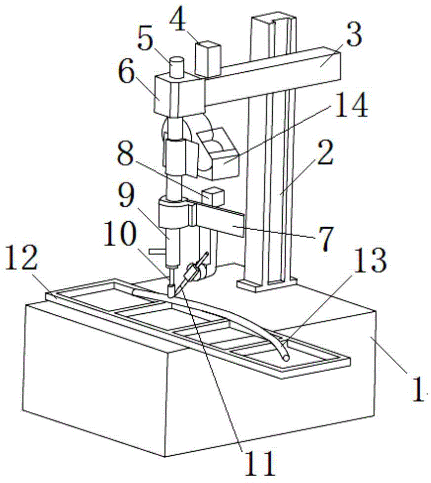
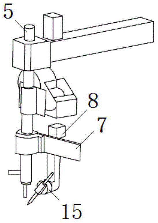
[0024] Such as figure 1 and figure 2 As shown, the automatic welding device includes a base 1, a column 2, a cross arm 3, a welding torch 11, and a wire feeder 14, wherein the lower end of the vertical column 2 is fixed on the base 1, and the base 1 is provided with a fixture 12, The welding workpiece 13 is positioned by the tooling fixture 12; one end of the cross arm 3 is fixed on the column 2, and the other end of the cross arm 3 is equipped with a spindle box 6 and a spindle motor 4, and the spindle box 6 is provided with a vertical spindle 5, through which the spindle motor 4 drives the main shaft 5 to rotate.

[0025] The wire feeder 14 for feeding welding wire to the welding torch is fixed on the middle part of the main shaft 5 and can rotate together with the main shaft. An X-axis s...


PUM


Abstract

The invention discloses an automatic welding device and a welding process thereof. The welding device comprises a vertical column, a transverse arm and a welding gun, wherein one end of the transverse arm is arranged on the vertical column, the other end of the transverse arm is provided with a main shaft and a main shaft motor, the main shaft motor is used for driving the main shaft to rotate, the main shaft is provided with a welding wire delivery machine, the welding wire delivery machine is used for delivering welding wires to the welding gun, the main shaft is provided with an X-axis slide rail, a Z-axis slide rail is arranged on the X-axis slide rail, a rotary body is arranged on the Z-axis slide rail, and the welding gun is arranged on the rotary body. The welding process comprises the following steps of utilizing a tooling clamp on a base to position a welding workpiece; enabling a manual pull rod on an elastic center rod to lift the elastic center rod, putting another welding workpiece under a press head, and pressing and positioning the two welding workpieces together; adjusting the position of the welding gun, and driving the main shaft and the slide rails to weld a welding seam; after welding, lifting the elastic center rod, ascending the press head, and taking off the welding workpieces. The automatic welding device and the welding process have the advantages that the pre-fixing for manual point welding is not needed, and the welding production efficiency is improved.

Description

technical field [0001] The invention relates to the field of welding technology, in particular to an automatic welding device and a welding process thereof. Background technique [0002] At present, compared with other types of metal forming processing, welding processing is not highly automated and relies more on manual operations. There are deficiencies in welding quality, work efficiency, personnel safety, energy saving and environmental protection. Although the welding robot industry has developed in recent years Rapid, powerful welding robot, but its price is expensive, unaffordable by ordinary small and medium-sized enterprises, and there is no common and open technology among robot manufacturers, so different brands of robots operate differently, and usually require professionals trained by manufacturers It can only be operated, which makes it difficult for robots to enter small and medium-sized enterprises with weaker technical strength for a while. [0003] In orde...

Claims


Application Information

Patent Timeline
IPC IPC(8): B23K9/02B23K9/12B23K9/00
CPCB23K9/12B23K9/32B23K37/0435
Inventor 张陆胜
Owner 芜湖胜帮机电设备有限公司
Learn More