Manufacturing method of strip-shaped stator core lamination and mold arrangement therefor

A belt-shaped stator, a technology for a manufacturing method, applied in a manufacturing method and a mold device for the same, and a mold device field, and can solve the problems of embedding and difficulty in separating the belt-shaped core pieces 95 from each other.

Active Publication Date: 2017-04-05
MITSUI HIGH TEC INC
View PDF7 Cites 0 Cited by
  • Summary
  • Abstract
  • Description
  • Claims
  • Application Information

AI Technical Summary

Problems solved by technology

[0011] In addition, when the front end of the magnetic pole piece 96 and the inner periphery of the yoke piece 97 are sheared within the elastic limit of the magnetic strip 98, there may be cases where the front end of the magnetic pole piece 96 tends to recover due to the tendency of the magnetic pole piece 96 to recover. Possibility of fitting into the inner circumference of the yoke piece part 97 due to the force of the original state
[0012] Thus, if the front end of the pole piece 96 is press-fitted into the inner circumference of the yoke piece 97, it may be difficult to mesh the pole pieces 96 when winding or winding the laminated strip-shaped core piece 95. The problem that the strip core pieces 95 are separated from each other

Method used


Image

  • Manufacturing method of strip-shaped stator core lamination and mold arrangement therefor
  • Manufacturing method of strip-shaped stator core lamination and mold arrangement therefor
  • Manufacturing method of strip-shaped stator core lamination and mold arrangement therefor

Examples


Embodiment Construction

[0059] Next, referring to the attached drawings, the embodiment of the present invention will be described for understanding of the present invention.

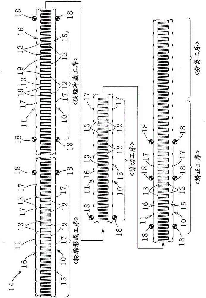
[0060] Such as figure 1 As shown, the method for manufacturing a strip-shaped stator core sheet according to an embodiment of the present invention includes first and second strip-shaped stator core sheets (hereinafter also simply referred to as strip-shaped core sheets) 10 and 11, and the strip-shaped The magnetic pole piece parts 12 and 13 of the core pieces 10 and 11 are discharged on the magnetic strip 14 in the meshed state, and the strip-shaped core pieces 10 and 11 are separated from the magnetic strip 14 by press working. Forming process, slit punching process, shearing process, straightening process and separation process. Next, it will be described in detail.

[0061] (preparation process)

[0062] The first and second strip-shaped core pieces 10 and 11 are laid out on a magnetic strip 14 made of an electromagnet...


PUM


Abstract

The invention discloses a manufacturing method of a strip-shaped stator core piece and a mold device used for it. In the present invention, it is a method of separating the first and second strip-shaped stator core pieces from the magnetic strip material discharged in the state where the magnetic pole pieces are engaged by pressing, and has the method of making the first and second strips The front end of each magnetic pole piece of the stator core piece is positioned on the inner periphery of the yoke iron piece between the magnetic pole pieces, and the slit punching process for forming the gap of each magnetic pole piece, cutting the front end of each magnetic pole piece And the shearing process of the inner circumference of each yoke piece, the straightening process of returning each pole piece bent by this process to its original state, and the first and second pole pieces pushed back by this process Separation process for strip-shaped stator core lamination separation.

Description

technical field [0001] The present invention relates to a method for manufacturing a strip-shaped stator core sheet used for manufacturing a laminated core and a mold device used therefor, and more specifically, to a method for manufacturing a laminated body for forming a laminated core by winding it in a spiral shape. A method of manufacturing strip-shaped stator core laminations and a mold arrangement therefor. Background technique [0002] In the past, such as Figure 8 As shown in (A), there is a laminated core (for example, See Patent Document 1). When forming the strip-shaped core sheet 90, as Figure 8 As shown in (B), the two strip-shaped core pieces 90 are discharged onto the magnetic bar 92 with the magnetic pole pieces 91 engaged, and punched to form, thereby improving the yield of the material. [0003] However, if Figure 8 As shown in (B), since the two strip-shaped core pieces 90 are discharged on the magnetic bar 92 into the front end of each magnetic pole ...

Claims


Application Information

Patent Timeline
Patent Type & Authority Patents(China)
IPC IPC(8): H02K15/02
CPCH02K15/026Y10T29/49009Y10T29/53161H02K15/024
Inventor 丰丸阳平宗冈秀策甲野善治
Owner MITSUI HIGH TEC INC
Why Eureka
Try Eureka