
Head-up display and method for improving time-sharing overlapping display effect

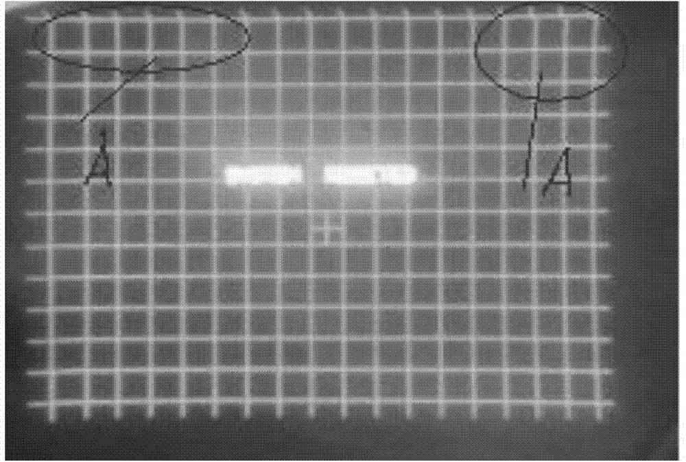
A head-up display and superimposed display technology, used in static indicators, cathode ray tube indicators, instruments, etc., can solve problems such as the inability of the electron beam to place the point in place, the character from the pen and the bright line, and the bending and deformation of the top of the grating, so as to improve the image. show effect

Active Publication Date: 2015-01-21
LUOYANG INST OF ELECTRO OPTICAL EQUIP OF AVIC
View PDF7 Cites 3 Cited by
  • Summary
  • Abstract
  • Description
  • Claims
  • Application Information

AI Technical Summary

Problems solved by technology

[0005] The purpose of the present invention is to provide a head-up display and a method for improving its time-sharing superimposed display effect, to solve the problem of the CRT image source due to the Due to the inherent response rate, the electronic beam cannot be placed in place when it jumps for a long distance, causing bright lines to appear at the beginning of the character, and bending deformation at the top of the grating

Method used


Image

  • Head-up display and method for improving time-sharing overlapping display effect
  • Head-up display and method for improving time-sharing overlapping display effect
  • Head-up display and method for improving time-sharing overlapping display effect

Examples


Embodiment Construction

[0020] The specific embodiments of the present invention will be further described below in conjunction with the accompanying drawings.

[0021] Embodiment of a head-up display of the present invention

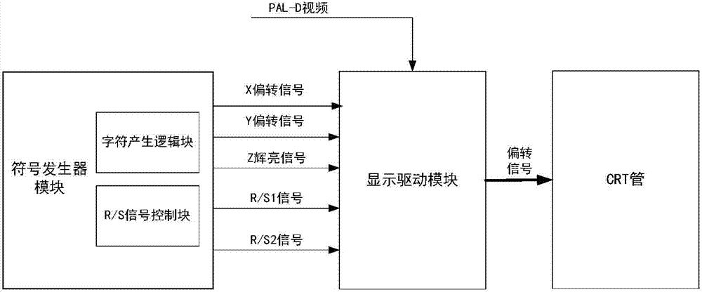
[0022] Such as figure 1 As shown, the head-up display of the present invention includes a generator module, a display driver module and a CRT tube, and the symbol generator module includes a character generation logic block and an R / S signal control block, wherein the character generation logic block is used to generate X deflection signals, Y The deflection signal and the Z highlighting signal, the R / S signal control block is used to generate two working mode control signals R / S1 and R / S2 according to the bus command, and the display driver module selects the pure stroke information (Z highlighting signal and X, Y deflection signal) or pure raster information (video signal and line, field sawtooth wave signal), drive the CRT tube to display pure stroke characters or pure ras...


PUM


Abstract

The invention relates to a head-up display and a method for improving the time-sharing overlapping display effect, and belongs to the technical field of airborne display equipment. Two control signals R / S1 and R / S2 are generated. In the display period of the head-up display, the changes of R / S1 and R / S2 are controlled to show that the head-up display works in a grating / stroke time-sharing overlapping mode. The rising edge timing sequences of R / S1 and R / S2 are the same, and the falling edge of R / S2 is delayed by a set period of time relative to the falling edge timing sequence of R / S1. With the falling edge of R / S1 as a benchmark and in a set period of time, a brightness signal is logically controlled by a character generator to be low, and the head-up display is forced to have no display. In a set period of time of the rising edges of R / S1 and R / S2, the brightness signal is controlled to be low, and the head-up display is forced to have no display. According to the method, delayed display is carried out at the rising edge (grating to stroke) and the falling edge (stroke to grating) of an R / S signal. The problem that the first stroke of a character is bright and the top end of a grating is bent and deformed in a grating / stroke overlapping state of the head-up display is solved, and the image display effect of the head-up display is improved.

Description

technical field [0001] The invention relates to a head-up display and a method for improving its time-sharing superimposed display effect, belonging to the technical field of airborne display equipment. Background technique [0002] The head-up display accurately projects the symbols that need to be displayed into the driver's front field of view, so that various information and real exterior information are superimposed together for the pilot to observe and judge the flight status, so the symbols and images displayed on it must be clear ,Stablize. [0003] At present, the mainstream HUD has three working modes: pure stroke character display, pure raster video display and raster / stroke time-divided superimposed display. The head-up display mainly includes a symbol generator module, a display driver module and a CRT tube and other components. The symbol generator module outputs the working mode control signals R / S1 and R / S2, and the display driver module selects pure stroke...

Claims


Application Information

Patent Timeline
IPC IPC(8): G09G1/00
Inventor 王灵刚汤礼平李洁刘俊峰
Owner LUOYANG INST OF ELECTRO OPTICAL EQUIP OF AVIC
Learn More