Temperature control system and temperature control method
A technology of temperature control system and main control system, which is applied in the direction of control/regulation system, temperature control, non-electric variable control, etc. It can solve problems such as burning circuit boards, overheating of the body, and failure to cut off power in time to achieve energy saving, The effect of guaranteeing the service life and preventing damage
- Summary
- Abstract
- Description
- Claims
- Application Information
AI Technical Summary
Problems solved by technology
Method used
Image
Examples
Embodiment approach 1
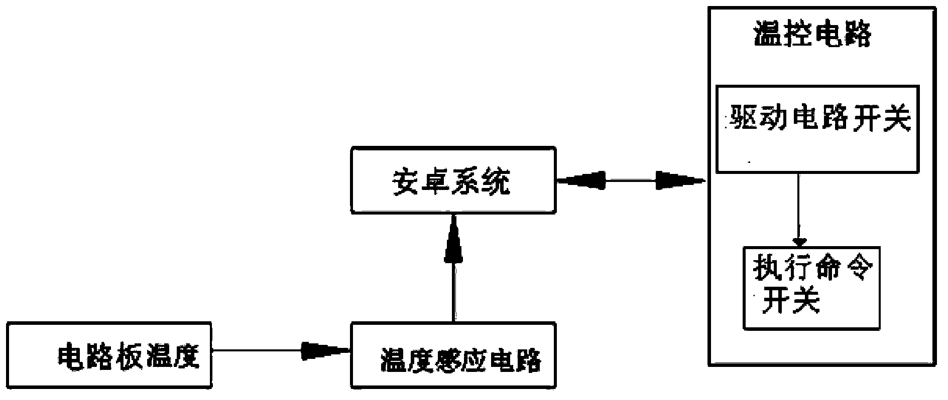
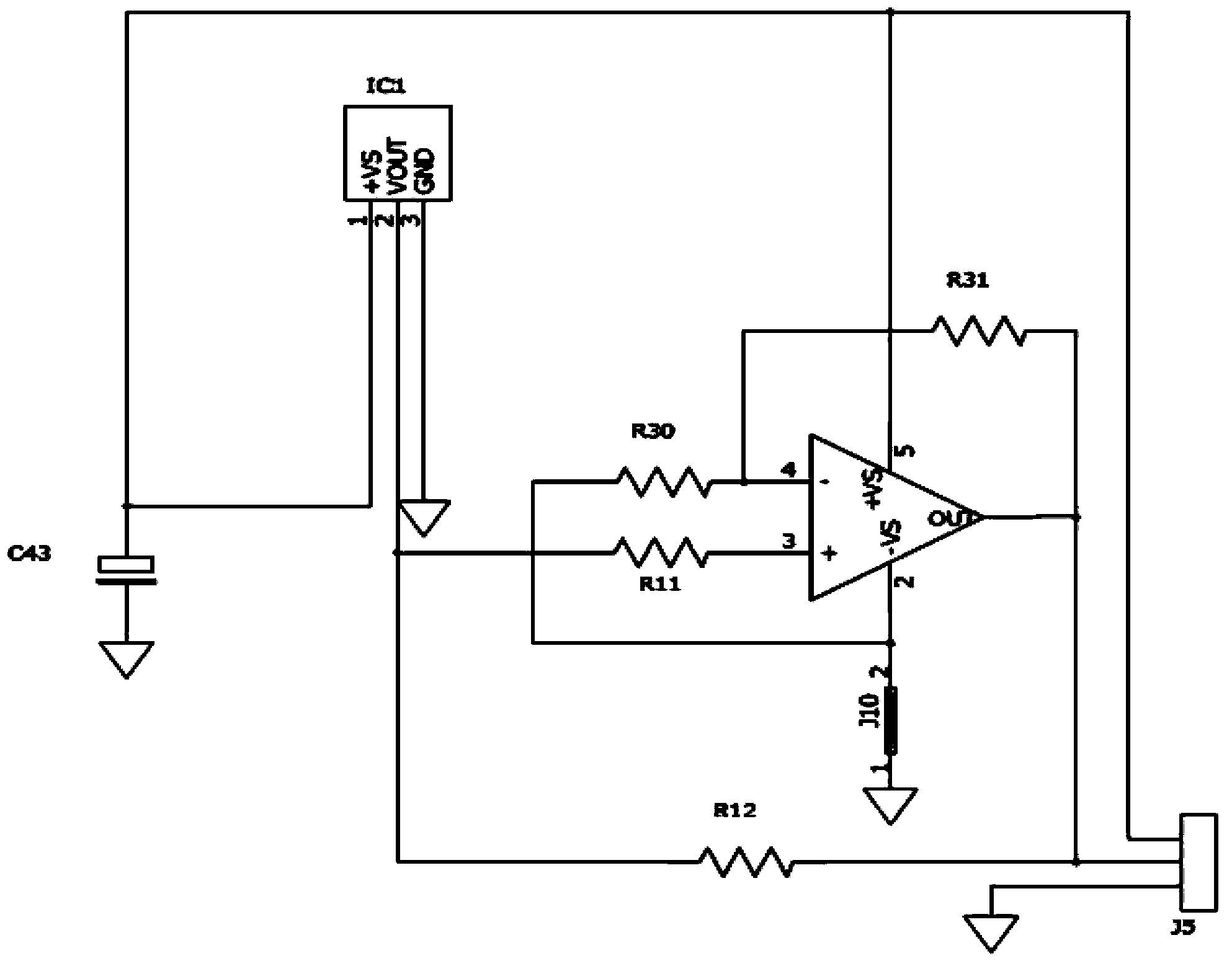
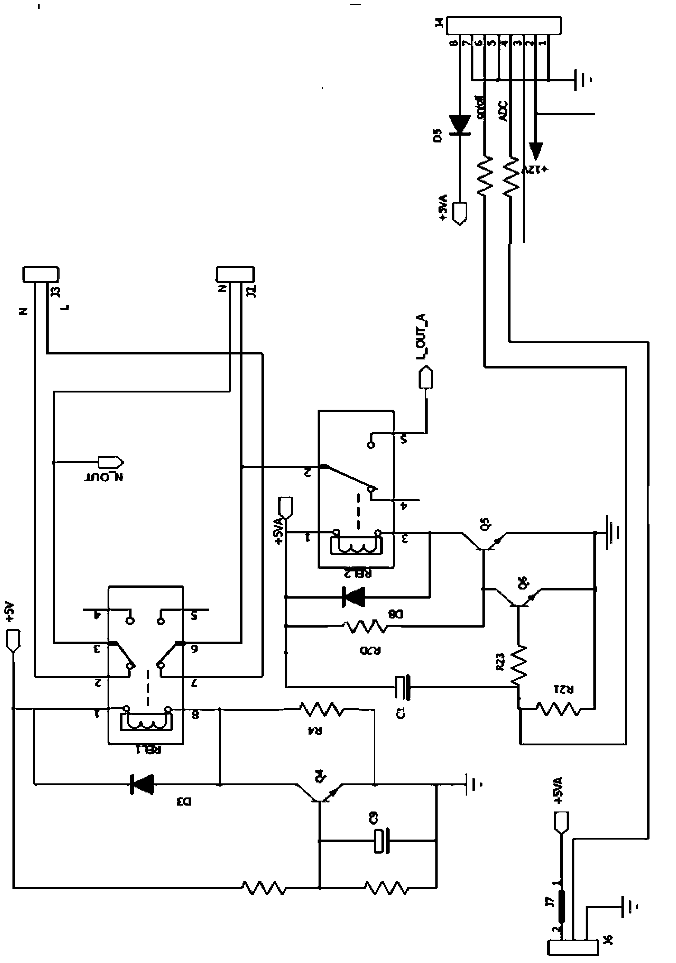
[0031] Implementation Mode 1: Refer to figure 1 , 2 3. A temperature control system, including a main control system, a temperature sensing circuit for detecting the temperature of the circuit board in the body, and a temperature control circuit for making temperature control instructions. The main control system controls the temperature sensing circuit and the temperature control circuit. The control circuit includes a power-off switch circuit for emergency power-off protection; the power-off switch circuit includes a double switch circuit of a drive circuit switch and an execution command switch, and the drive circuit switch controls the execution command switch. The drive circuit switch includes the J4 pin 6, Q6 and Q5 two-stage amplifiers that accept the power-off command and the switch REL2 that turns on / off the drive circuit, and the collector of the Q5 amplifier is connected to the 3 pins of the switch REL2; The command switch includes the Q4 amplifier and the switch R...
Embodiment approach 2
[0033] Implementation mode two: refer to figure 2 , 3 4. On the basis of Embodiment 1, the main control system is also connected with a display screen.
[0034]When working, the temperature control method of the above temperature control system is as follows: the temperature sensor IC1 detects the temperature in the circuit board of the infrared touch all-in-one machine, outputs an electrical signal, and sends the signal to be amplified by the amplifier IC5, and then passed to the connector J5, using a wire The connection method sends the signal to the Android system. The Android system is equipped with power-off protection to control the temperature at 80°C (the temperature at which components are easily damaged). When the temperature read by the Android system reaches 80°C, the Android system will display a prompt character "The temperature inside the machine is too high and the power will be cut off soon" through the LED LCD screen. , please check the heat exhaust blocka...
Embodiment approach 3
[0035] Implementation Mode Three: Refer to figure 2 , 3 , 5, 6, on the basis of the second embodiment, the only difference is that the temperature control circuit also includes a cooling drive circuit. The cooling drive circuit includes a connector J4 pin 3 that accepts instructions, a J8 connector connected to the fan, and a transistor Q1 that controls the fan switch. The connector J4 pin 3 is connected to the base of the transistor Q1, and the J8 connector pin 2 is connected with the collector of transistor Q1. The base of the triode Q1 is connected in series with a voltage dividing resistor R1, and the base of the triode Q1 is also connected in parallel with two shunt resistors R2 and R3.
[0036] When working, the temperature control method of the above temperature control system: the temperature sensor IC1 detects the temperature in the circuit board of the infrared touch all-in-one machine, outputs an electrical signal, and sends the signal to be amplified by the ampl...
PUM
 Abstract
Description
Claims
Application Information
 - R&D
- Intellectual Property
- Life Sciences
- Materials
- Tech Scout
- Unparalleled Data Quality
- Higher Quality Content
- 60% Fewer Hallucinations
Browse by: Latest US Patents, China's latest patents, Technical Efficacy Thesaurus, Application Domain, Technology Topic, Popular Technical Reports.
© 2025 PatSnap. All rights reserved.Legal|Privacy policy|Modern Slavery Act Transparency Statement|Sitemap|About US| Contact US: help@patsnap.com


