
Aircraft engine tail profile measurement device and method based on machine vision

A technology for aircraft engine and contour measurement, applied in the direction of measuring devices, optical devices, instruments, etc., can solve the problems of slow measurement speed, high tail temperature, large size, etc., and achieve the effect of improving accuracy and increasing reliability

Inactive Publication Date: 2015-01-21
UNIV OF ELECTRONICS SCI & TECH OF CHINA
View PDF5 Cites 5 Cited by
  • Summary
  • Abstract
  • Description
  • Claims
  • Application Information

AI Technical Summary

Problems solved by technology

The basic principle of contact measurement is that the machine takes points one by one, the measuring head is in contact with the measured object, the operation process is cumbersome, and the measurement speed is slow, especially when the measured object is large, it is very time-consuming
Because of the high temperature and large size of the tail of the aircraft engine when it is working, the traditional contact three-dimensional measurement method is no longer applicable

Method used


Image

  • Aircraft engine tail profile measurement device and method based on machine vision
  • Aircraft engine tail profile measurement device and method based on machine vision
  • Aircraft engine tail profile measurement device and method based on machine vision

Examples


Embodiment Construction

[0041] For the interference of strong background light at the tail of the engine, we used laser lock-in imaging technology. The basic principle of lock-in imaging is the weak signal detection principle widely used in phase-locked loops, including two processes of multiplication and low-pass filtering. For locked imaging of digital images, multiplication and low-pass filtering become digital multiplication and digital low-pass filtering operations, which can be realized by software. Lock-in imaging can generally extract weak image signals that are more than 200 times lower than noise; while optical filters can filter out about 90% of background light. The image acquisition technology that combines optical filtering and digital lock-in imaging is called laser lock-in imaging technology. This technology has unparalleled ability to suppress background light. Experiments have shown that when the intensity of the background light is 104 times greater than that of the target scatte...


PUM


Abstract

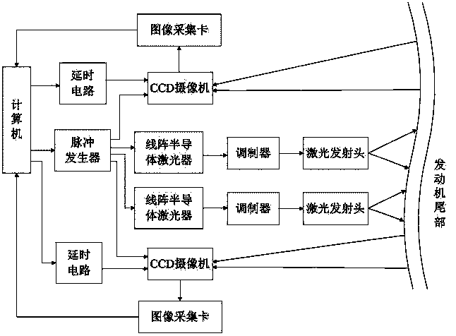
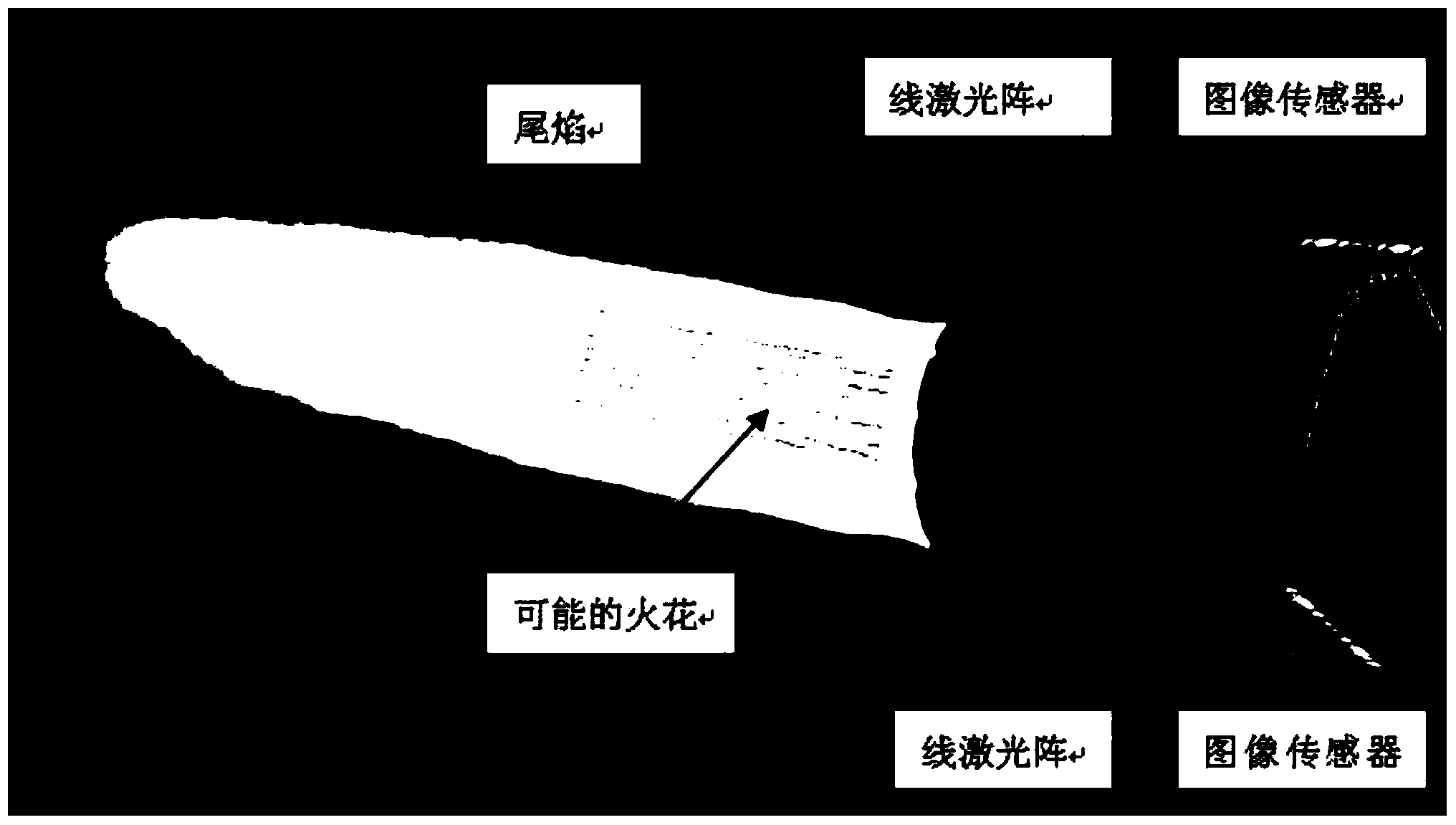
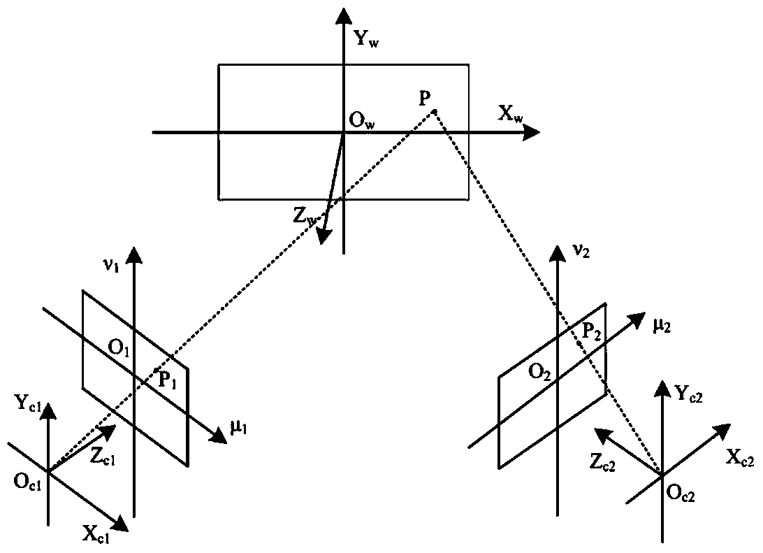
The invention discloses an aircraft engine tail profile measurement device and method based on machine vision. The device comprises a computer, two CCD cameras, two linear array semiconductor lasers and modulators. The output of the computer is connected with a pulse generator, the pulse generator is connected with the CCD cameras and the linear array semiconductor lasers, the linear array semiconductor lasers are connected with laser emission heads through the modulators, and the CCD cameras capture linear array profiles and upload the linear array profiles to the computer through image acquisition cards. The measurement method includes the steps that the CCD cameras capture images respectively, profile diagrams are acquired from strong light in a laser lock-on imaging mode, and after the profiles are corrected, the images acquired by the two CCD cameras are fused. According to the aircraft engine tail profile measurement device and method based on machine vision, the two CCD cameras are used for partially capturing the profile diagrams of the linear arrays of the tail of an engine in the field of view and capture flames on the tail in the field of view, the working conditions of the engine are studied in the aspect of tail flame images and the aspect of tail profile changes, and thus the reliability of detection is improved.

Description

technical field [0001] The invention belongs to the field of aero-engine performance detection, relates to technologies such as image processing, laser and optics, and computer, and proposes a method for measuring the profile of the tail of an aircraft engine and analyzing tail flames, and specifically relates to a device for measuring the profile of the tail of an aircraft engine based on machine vision and methods. Background technique [0002] With the rapid development of the national economy, air transport is becoming more and more important in people's lives. With its fast, comfortable, and relatively safe characteristics, airplanes have gradually become the most important way of travel for people. But in recent years, the accident rate of aircraft has increased greatly, so enhancing the flight safety of aircraft has become a task that cannot be ignored, and the working performance of aircraft engine is an important part of aircraft flight safety, and its state direct...

Claims


Application Information

Patent Timeline
Patent Type & Authority Applications(China)
IPC IPC(8): G01B11/245
Inventor 余学才张行至余瑞华程小龙
Owner UNIV OF ELECTRONICS SCI & TECH OF CHINA
Learn More