
Wind power generation device with rear-mounted blades

The utility model relates to a wind power generation device and a rear-mounted technology, which is applied in the directions of wind power generation, wind turbines, and wind turbines in the same direction as the wind, and can solve the problems of incapable of making full use of the ascending airflow, complicated blade folding, and being easily damaged by strong winds, etc. Achieve the effect of improving anti-bending performance, reducing flocculation interference, and reducing wind energy loss

Active Publication Date: 2015-01-21
丁健威
View PDF6 Cites 4 Cited by
  • Summary
  • Abstract
  • Description
  • Claims
  • Application Information

AI Technical Summary

Problems solved by technology

[0004] One of the objectives of the present invention is to provide a wind power generation device with rear blades to solve the problems in the prior art that the cost of a single independent column is high, and the addition of cable-stayed steel cables affects the blades
In particular, the poor adaptability to the mountainous environment and the inability to make full use of technical problems such as climbing updrafts
[0005] The second object of the present invention is to provide a wind power generation device with rear blades to solve the technical problems of weak ability to avoid strong winds, easy damage by strong winds, complicated and troublesome folding of blades, etc.

Method used


Image

  • Wind power generation device with rear-mounted blades
  • Wind power generation device with rear-mounted blades
  • Wind power generation device with rear-mounted blades

Examples


Embodiment 1

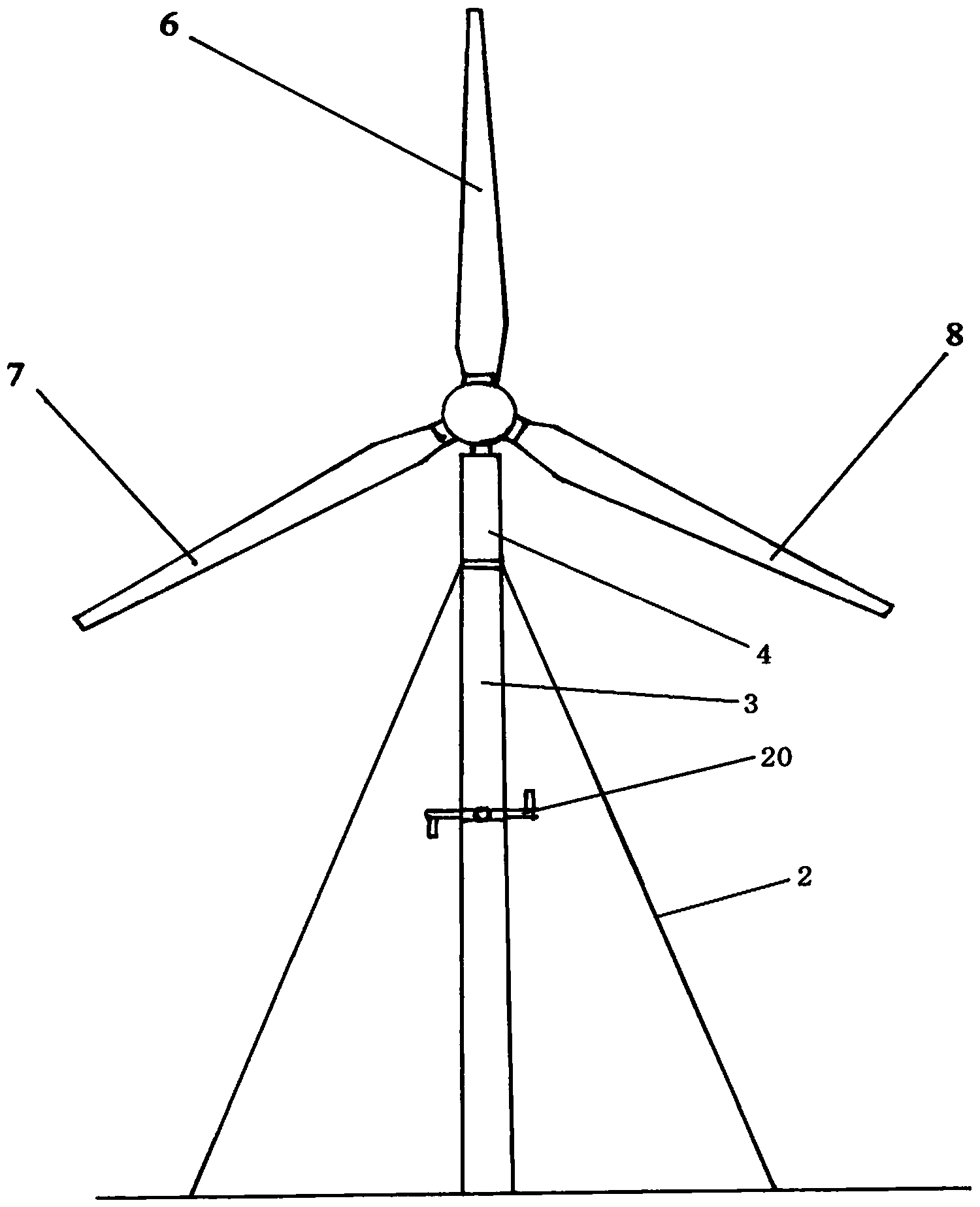
[0031] Embodiment one: see figure 1 — Figure 4 , The main body of the wind power generation device in this embodiment includes a hydraulic piston cylinder 1, a steel cable 2, a column 3, a casing 4, a main engine 5, a fixed blade 6, movable blades 7, 8 and ground piles. The four steel cables 2 are pulled diagonally from the upper part of the column 3 to the ground and fastened to the ground pile. The bottom center and rear of the main machine 5 are respectively provided with hinges, and the upper part of the column 3 is provided with a sleeve 4 that can rotate 360°. The top of the pipe 4 is hinged with the bottom center of the main engine 5 through the shaft pin 9 . The hydraulic piston cylinder 1 is supplied and recovered by a small hydraulic station that can be remotely controlled, and by manipulating the telescopic movement of the piston of the hydraulic piston cylinder 1, the pitch angle change of the main engine 5 on the column 3 can be adjusted. When the piston of the h...

Embodiment 2

[0033] Example 2: see Figure 5 — Figure 9 , this embodiment is the process of unfolding and folding the blades on the power shaft 16. In this embodiment, the power shaft 16 of the main engine 5 is installed on the main shaft 22 through the rolling bearing 23, and one end of the power shaft 16 is provided with a circular baffle 13. The baffle 13 is machined with a plurality of pin holes 26 (26A) for connecting the blade seat 27, the other end of the power shaft 16 is provided with a gear 18 and a gear step 19, and the gear step 19 is provided with a pin hole 26 of the circular baffle 13. Corresponding concentric pin holes, the gear 18 transmits power to the main engine 5 responsible for power generation, and the action motor 21 meshes with the gear 18, wherein the blade seat of the fixed blade 6 is fixed by the long cylindrical pin 24 through the connecting pin hole 14 and the pin hole 26 in an interpenetrating manner. Connected between the circular baffle 13 and the gear st...


PUM


Abstract

The invention discloses a wind power generation device with rear-mounted blades. The wind power generation device comprises a stand column, a wind power generation main engine and the blades. The main engine is hinged to the top of the stand column. The blades are installed on the tail of the main engine in a rear-mounted mode. A hydraulic piston cylinder capable of moving telescopically is further hinged between the upper portion of the stand column and the rear portion of the main engine. A piston of the hydraulic piston cylinder moves telescopically to adjust changes of the pitching dip angle, on the stand column, of the main engine. At least three steel cables are uniformly distributed on the upper portion of the stand column and fixedly connected to the upper portion of the stand column. The other ends of the steel cables are fixedly connected with a ground pile in a cable-stayed mode. Due to the design, the steel cables of the stand column and the blades do not interfere with each other in the cable-stayed process of the cables, wind resistance influence is small, diameter space of the blades is enlarged, the swept area of wind power is increased, power is increased, the dip angle can be controlled, adjusted and rotated for harmonizing loads of wind power, and the wind power can be tracked automatically; due to high-gradient hilly area arrangement, the blades rotate in an inclined mode to make the front side face wind, and the wind power is fully utilized; with assistance of the cable-stayed steel cables, the structural cost can be reduced, the defect of the poor wind-proof capacity in tradition is overcome, and the wind power generation device is suitable for being arranged on coasts with strong wind.

Description

technical field [0001] The invention relates to a wind energy utilization device, in particular to a wind power generator whose blades are placed behind a column to rotate and the blades can be folded. Background technique [0002] In the conventional wind power generators that are common at present, the main engine used for power generation is installed horizontally on the top of the column, and the blades are arranged in front of the column. The layout feature of this type of front-mounted horizontal axis wind turbine is that the front of the blade rotates around the horizontal axis against the wind and is not disturbed by the floc flow of the column, but its disadvantage is that when the wind intensity increases, the vertical column will bear a large force Horizontal thrust; the blades and main equipment are arranged at the top of the column, which is heavy and the center of gravity is high. The column is made of steel in the design, and the installation requirements are ...

Claims


Application Information

Patent Timeline
Patent Type & Authority Applications(China)
IPC IPC(8): F03D9/00F03D7/04F03D1/06
CPCF03D1/065F03D1/0658F03D7/04F05B2270/321F05B2270/604Y02E10/72
Inventor 丁健威谢晓山
Owner 丁健威
Learn More