
High performance soft magnetic composite Ni-Zn ferrite material

A ferrite material and soft magnetic composite technology, applied in the field of soft magnetic ferrite, can solve the problems of product bursting, affecting reliability, damage and so on

Inactive Publication Date: 2015-01-21
CYGE ELECTRONIC TECH (HUNAN) CO LTD
View PDF4 Cites 13 Cited by
  • Summary
  • Abstract
  • Description
  • Claims
  • Application Information

AI Technical Summary

Problems solved by technology

Since the high temperature during soldering will produce instantaneous thermal shock, it is also required that the product can withstand the stress generated by the thermal shock, otherwise the product will burst; and based on the current needs of electronic component assembly automation, components will After the movement, positioning, assembly, and welding of various mechanical fixtures, if the components do not have good mechanical strength, they may be damaged, which will affect their reliability.

Method used


Image

  • High performance soft magnetic composite Ni-Zn ferrite material
  • High performance soft magnetic composite Ni-Zn ferrite material
  • High performance soft magnetic composite Ni-Zn ferrite material

Examples


preparation example Construction

[0039] The preparation method of above-mentioned formula is:

[0040] 1) Mixing for one-time sanding: mix ingredients according to the main formula and add 1.0 wt % PVA for wet sanding, where the mass ratio of (material: ball: water) is (1:8:0.6), and the sanding time is 1.0Hr ~1.5 Hr;

[0041] 2) Spray drying: Dry and granulate the sanded slurry with a pressure sprayer to make spherical granules. The drying temperature is controlled at 300°C~360°C and the pressure is controlled at 2.0~2.4MPa;

[0042] 3) Pre-burning: Send the sprayed pellets to the rotary kiln for pre-burning, the pre-burning temperature is controlled at 900°C±20°C, and the pre-burning time is 2.0Hr~3.5Hr;

[0043] 4) Secondary sanding: Add the specified amount of trace additives, pre-fired main component materials, and 2.0 wt % PVA into the sand mill for sanding, and the ratio of (material: ball: water) is ( 1:8:0.6), sanding time is 2.0Hr~3.0Hr;

[0044] 5) Centrifugal granulation: Dry the sanded slurry ...

Embodiment

[0061] The DC bias data of the embodiment is as follows: (unit: uH)

[0062]

[0063] The comparison ratio DC bias data is as follows: (unit: uH)

[0064]

[0065] Note: The source of the comparative example is the same model product of a famous domestic company, and the magnetic characteristics are: Bs=410mT, ui=360;

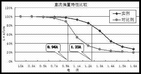
[0066] from figure 1 It can be seen that the bias curve characteristic of the embodiment of the present invention is obviously better than that of the comparative example. When maintaining the same inductance value of 80%, the embodiment is 1.23A while the comparative example is only 0.94A, which is 30% higher than that of the embodiment.

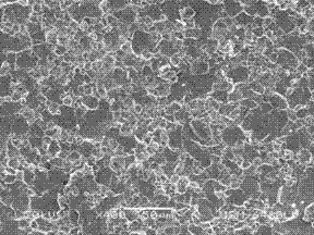
[0067] By adding TiO 2 、 Bi 2 o 3 Substances that can make the crystallization and refinement of the material uniform in pores (see attached figure 2 ); and because the stress generated by the instantaneous thermal shock will be transmitted through the grains and gradually decrease, so the refined grains can damp...


PUM


Abstract

The invention provides a thermal shock resistant Ni-Zn ferrite material with high saturation magnetic flux density. The material provided by the invention is suitable for manufacturing miniaturized power inductance magnetic cores. The material has a main formula composed of the following components and content: 48-50mol% of Fe2O3, 20-25mol% of ZnO, 25-30mol% of NiO, and 2-5mol% of CuO; trace additives comprise: 0.01-0.05wt% of Co2O3, 0.05-0.15wt% of TiO2 and 0.02-0.1% of Bi2O3. A twice wet process is employed to prepare the materials into powder, and the product is prepared by dry pressing molding, high temperature sintering, and electric polarization. The product has the characteristics of high saturation magnetic flux density, high direct current bias and thermal shock resistance, and can simultaneously satisfy the large power and soldering resistance (resistance to instantaneous thermal shock) requirements of small patch (SMD) inductance magnetic cores.

Description

technical field [0001] The invention relates to the technical field of soft magnetic ferrite, in particular to a high-performance soft magnetic composite Ni-Zn ferrite material. Background technique [0002] The current soft ferrite materials mainly include Mn-Zn series and Ni-Zn series, which are mainly used in the fields of computers, communications, power supplies and consumer electronics products, and are the basic materials of the electronics industry. Compared with Mn-Zn ferrite materials, Ni-Zn ferrite materials have the characteristics of high resistivity and high frequency of use, and are suitable for making surface mount components (SMD); Consumer electronic products such as computers, televisions, automobiles, and lighting tend to be small and thin. Similarly, the inductance components used must be further miniaturized. At the same time, it is required to maintain or improve its DC bias characteristics after the components are miniaturized to ensure their power u...

Claims


Application Information

Patent Timeline
IPC IPC(8): C04B35/26C04B35/622
CPCC04B35/2666C04B41/009C04B41/5116C04B2235/3232C04B2235/3279C04B2235/3281C04B2235/3284C04B2235/3298C04B2235/606C04B2235/656
Inventor 苏立良
Owner CYGE ELECTRONIC TECH (HUNAN) CO LTD
Learn More