
A control method and device for a bridgeless PFC circuit

Active Publication Date: 2018-11-16
ZTE CORP
View PDF5 Cites 1 Cited by
  • Summary
  • Abstract
  • Description
  • Claims
  • Application Information

AI Technical Summary

Problems solved by technology

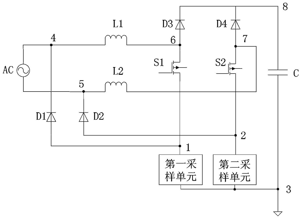
[0004] In the currently widely used dual-boost bridgeless PFC topology circuit, there are two boost inductors and two MOS transistors, and the structure is complex. Therefore, the current sampling and control methods are also very complicated.

Method used


Image

  • A control method and device for a bridgeless PFC circuit
  • A control method and device for a bridgeless PFC circuit
  • A control method and device for a bridgeless PFC circuit

Examples


Embodiment Construction

[0067] The preferred embodiments of the present invention will be described in detail below in conjunction with the accompanying drawings. It should be understood that the preferred embodiments described below are only used to illustrate and explain the present invention, and are not intended to limit the present invention.

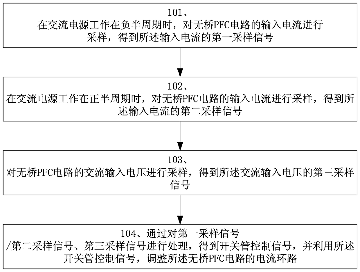
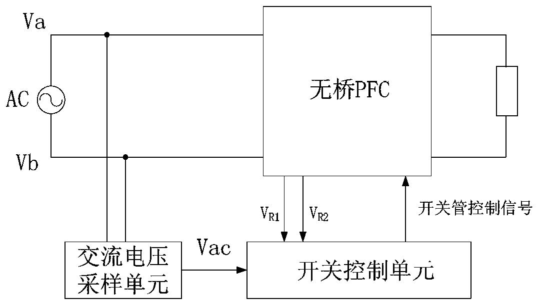
[0068] figure 1 It is a functional block diagram of the control method of the bridgeless PFC circuit provided by the embodiment of the present invention, such as figure 1 As shown, the steps include:

[0069] Step 101 , when the AC power supply is working in the negative half cycle, sampling the input current of the bridgeless power factor correction PFC circuit to obtain a first sampling signal of the input current.

[0070] When the AC power supply works in the negative half cycle, the input current of the bridgeless PFC circuit is the sum of the currents flowing through the first switching tube branch and the first return current branch of the bridgel...


PUM


Abstract

The invention discloses a method for controlling a bridgeless PFC circuit and a device thereof, which relates to the technical field of power supply power factor correction. The method comprises the steps of: when an AC power supply operates in a negative half period, sampling an input current to the bridgeless PFC circuit, and obtaining a first sampling signal of the input current; when the AC power supply operates in a positive half period, sampling the input current of the bridgeless PFC circuit, and obtaining a second sampling signal of the input current; sampling the AC input voltage of the bridgeless PFC circuit, and obtaining a third sampling signal of the AC input voltage; and through processing the first sampling signal, the second sampling signal and the third sampling signal, obtaining a switch tube control signal, and adjusting the current loop of the bridgeless PFC circuit through the switch tube control signal. The method of the invention can be used for sampling the input current simply and effectively, thereby controlling and realizing AC input voltage tracking by input current.

Description

technical field [0001] The invention relates to the technical field of power factor correction PFC, in particular to a control method and device for a bridgeless PFC circuit. Background technique [0002] Power factor correction PFC technology can realize the input current at the input terminal of the power supply to track the AC input voltage, thereby greatly reducing the reactive power in the grid and reducing the pollution of the power supply to the grid. [0003] With the development of technology, in order to improve the conversion efficiency of power supply, PFC technology has developed from traditional bridge PFC to bridgeless PFC. [0004] In the currently widely used dual-boost bridgeless PFC topology circuit, there are two boost inductors and two MOS transistors, and the structure is complicated. Therefore, the current sampling and control methods are also very complicated. [0005] How to simply and effectively sample the input current, so as to control and reali...

Claims


Application Information

Patent Timeline
Patent Type & Authority Patents(China)
IPC IPC(8): H02M1/42
CPCH02M1/4225Y02B70/10Y02P80/10
Inventor 梅纯鲍胜华涂大锐
Owner ZTE CORP
Learn More