Vehicular lighting unit

A lamp body and vehicle technology, which is applied to road vehicles, vehicle parts, motor vehicles, etc., can solve the problems of increasing the size of the lamp body, and achieve the effects of improving visual recognition, suppressing enlargement, and suppressing the increase in the number of parts.

Active Publication Date: 2015-01-14
HONDA MOTOR CO LTD
View PDF6 Cites 9 Cited by
  • Summary
  • Abstract
  • Description
  • Claims
  • Application Information

AI Technical Summary

Problems solved by technology

However, simply increasing the number of tail stop lamps will increase the size of the vehicle lamp body

Method used


Image

  • Vehicular lighting unit
  • Vehicular lighting unit
  • Vehicular lighting unit

Examples


Embodiment Construction

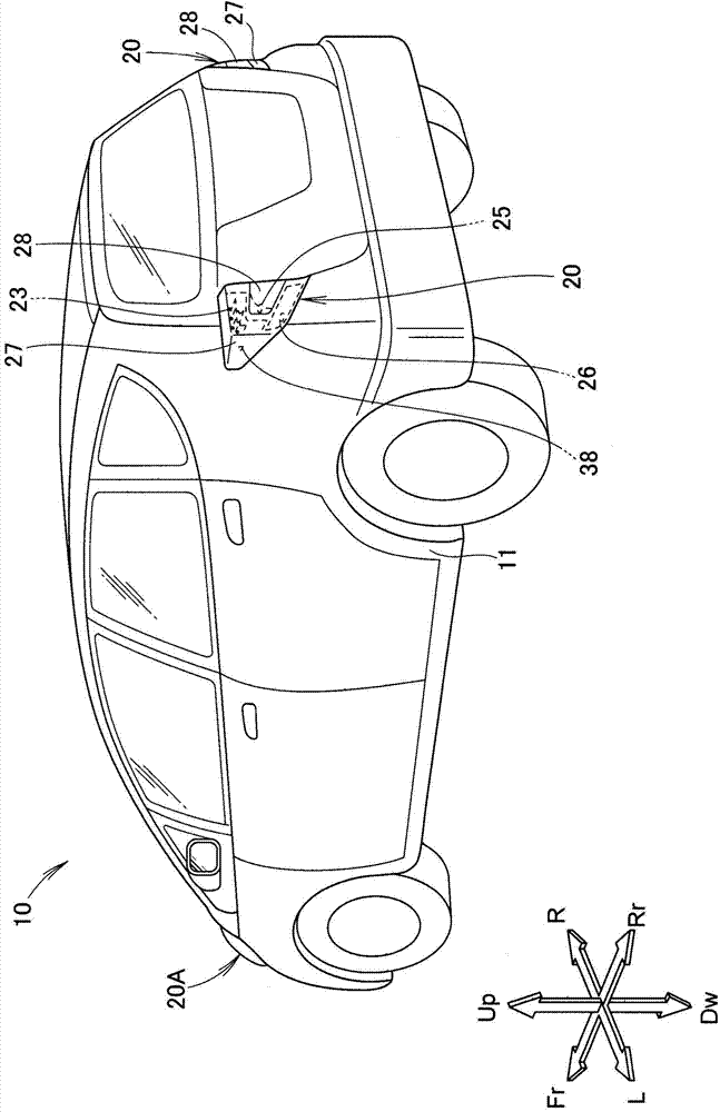
[0032] Hereinafter, embodiments of the present invention will be described based on the drawings. In addition, in the description, the left and right refer to the left and right based on the occupant of the vehicle, and the front and rear refer to the front and rear based on the traveling direction of the vehicle. In the figure, Fr indicates the front, Rr indicates the rear, L indicates the left as viewed from the occupant, R indicates the right as viewed from the occupant, Up indicates up, and Dw indicates down.

[0033] Such as figure 1 As shown, left and right tail lamp units 20 , 20 (vehicle lamp bodies 20 , 20 ) are attached to the rear portion of a vehicle body 11 forming the skeleton of the vehicle 10 .

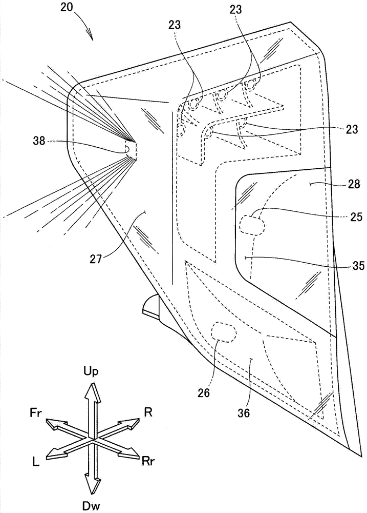
[0034] The left and right tail lamp units 20 and 20 of the present invention are not only formed bilaterally symmetrically, but also have the same basic structure. Hereinafter, the left tail light unit 20 will be specifically described as an example. The description...


PUM


Abstract

A vehicular lighting unit includes: a first light source in the form of an LED for providing illumination forward or rearward of a vehicle body, the first light source being mounted on one surface of a base plate in an orientation corresponding to the direction of the illumination; a second light source in the form of an LED for providing illumination laterally outward of the vehicle body, the second light source being mounted on another surface of the base plate; and a reflection section provided near the second light source for reflecting light emitted from the second light source laterally outward of the vehicle body

Description

technical field [0001] The present invention relates to an improved vehicle lamp body. Background technique [0002] There exists the technique disclosed in patent document 1 as the prior art of the lamp|ramp body for vehicles. [0003] As in the tail lamp unit as a lamp body for a vehicle shown in Patent Document 1, a tail stop lamp as a light source is attached to a lamp box. Based on the front-rear direction of the vehicle, the rear brake light is installed obliquely toward the outside of the vehicle. By installing it obliquely, the rear stop lamp can illuminate the rear and sides of the vehicle. That is, the tail light unit also functions as a side marker. [0004] The lamp body for a vehicle has the purpose of identifying the vehicle to a third party outside the vehicle. As one of methods for making a third party recognize the vehicle, it is conceivable to increase the number of rear stop lights and make them brighter. However, simply increasing the number of tail ...

Claims


Application Information

Patent Timeline
Patent Type & Authority Applications(China)
IPC IPC(8): F21S8/10F21V19/00F21V7/00F21W101/02F21W101/14F21Y101/02F21W107/10
CPCB60Q1/30B60Q1/2607B60Q1/32F21S43/13F21S43/14
Inventor 河村和幸松本昌朋青山和生铃木谦一
Owner HONDA MOTOR CO LTD
Why Eureka
Try Eureka