Eureka AIR delivers breakthrough ideas for toughest innovation challenges, trusted by R&D personnel around the world.

Support enabling switching between horizontal watching state and looking-up watching state to be achieved rapidly in one-step mode

A technology of rapid switching and rotating shaft, applied in the direction of machine/stand, supporting machine, mechanical equipment, etc., can solve the problems of not meeting the requirements of head-up, inconvenient to widen the viewing distance, complicated angle adjustment structure, etc., to achieve convenient production and processing, The effect of low production cost and simple structure

Active Publication Date: 2015-01-14
王铁
View PDF15 Cites 8 Cited by
  • Summary
  • Abstract
  • Description
  • Claims
  • Application Information

AI Technical Summary

Problems solved by technology

[0005] The patent number is 201110211829.2, and the name is the invention patent of "An Angle-Adjustable TV Hanger", which realizes the angle adjustment of the flat-panel TV through the cooperation of the adjustment pin and the card position in the keyway, and it does not have the lifting function; in addition, its The angle adjustment structure is also more complicated
When adjusting the angle, you need to pull the pull cord to control the adjustment pin to enter and exit the card slot through the movement of the inclined block; it has the following disadvantages: 1. The size of the inclined block is proportional to the tilt angle of the TV; big
[0010]There are also some ceiling-mounted TV stands, although they meet the requirements of looking up, they cannot meet the requirements of looking up, cannot be lowered low enough, and cannot be attached to the wall. It takes up a lot of space, and it is inconvenient to increase the viewing distance

Method used


Image

  • Support enabling switching between horizontal watching state and looking-up watching state to be achieved rapidly in one-step mode
  • Support enabling switching between horizontal watching state and looking-up watching state to be achieved rapidly in one-step mode
  • Support enabling switching between horizontal watching state and looking-up watching state to be achieved rapidly in one-step mode

Examples


Embodiment Construction

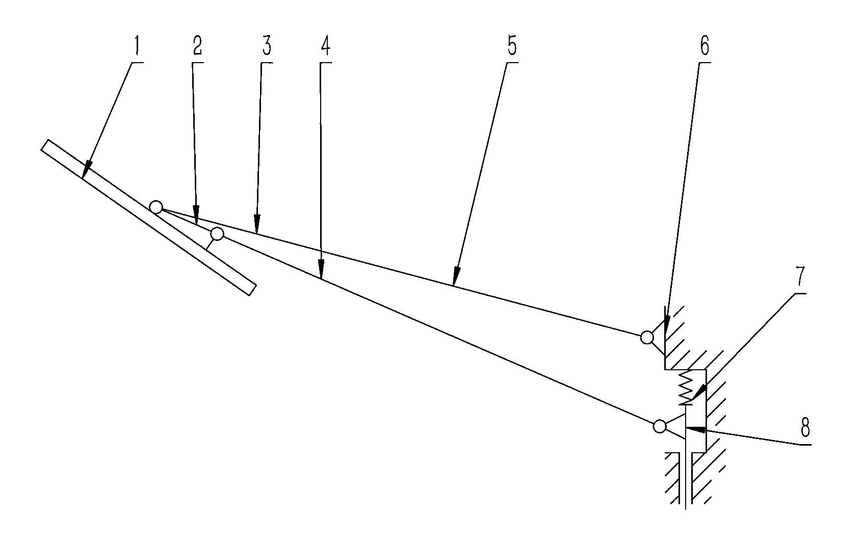
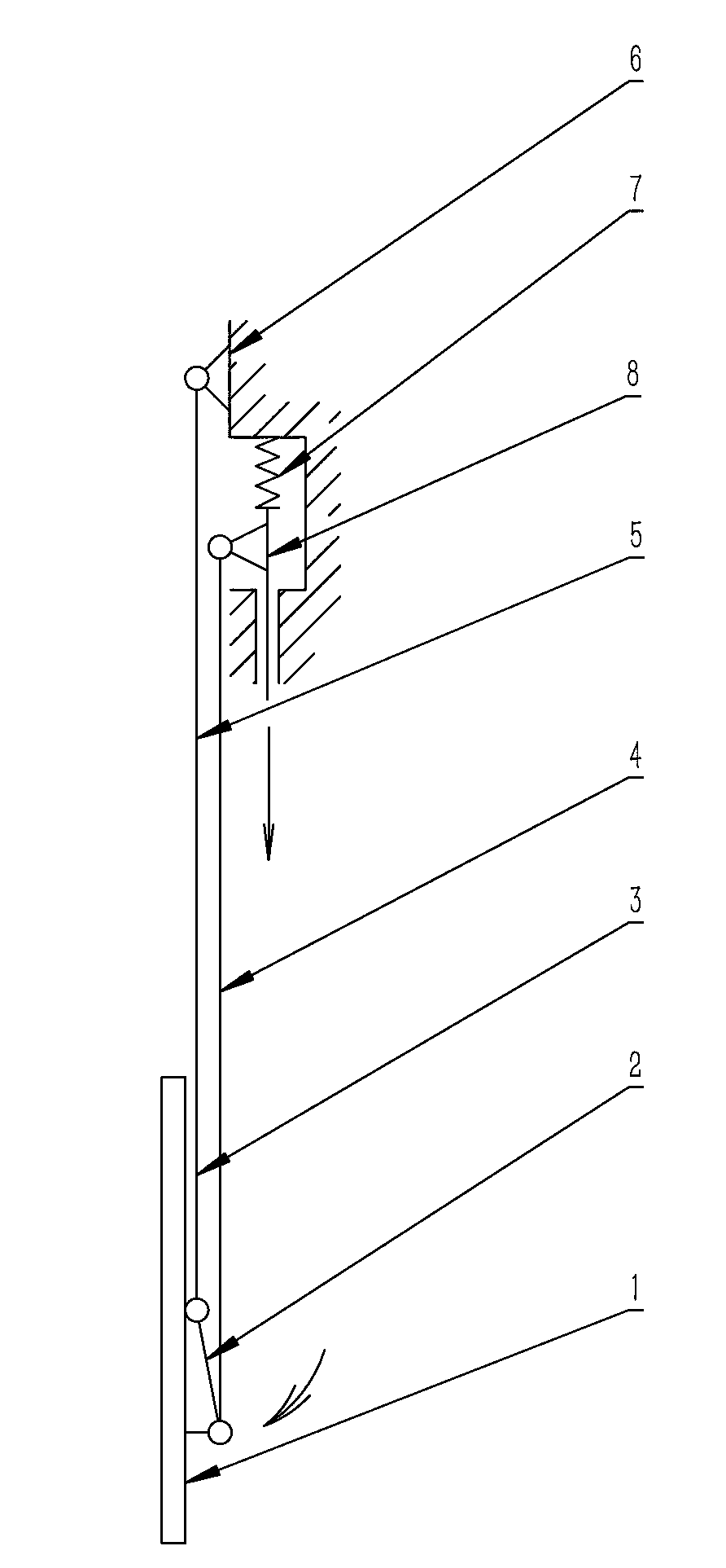
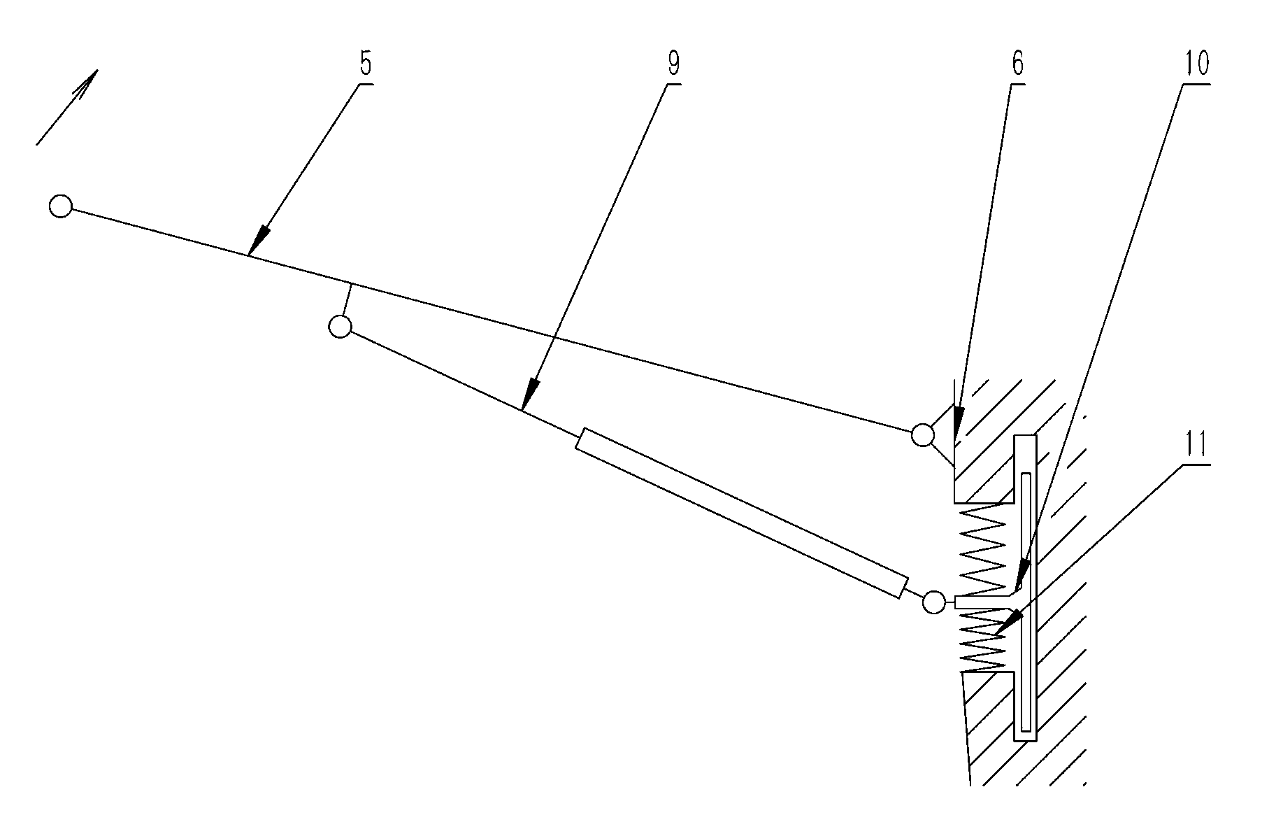
[0039] The present invention includes a four-bar linkage mechanism 5 hinged end-to-end sequentially by a frame base 6, an upper rocker arm 3, a link rod 2, and a lower rocker arm 4, and is characterized in that it also includes a telescopic rod 9, and the telescopic rod 9 One end is hinged with the frame seat 6, and the other end of the telescopic rod 9 is hinged with the upper rocker arm 3 or the lower rocker arm 4.

[0040] As a preferred solution of the present invention, the telescopic rod 9 is a gas spring or an electric push rod.

[0041] Further, the gas spring is provided with a self-locking point in the rotation path.

[0042] Furthermore, the gas spring is slidingly hinged with the frame seat 6 through the displacement buffer device 10 .

[0043] The displacement buffer device 10 includes a limiting plate 26 fixed on the frame base 6, and a limiting groove 33 is arranged on the limiting plate 26; Groove 33 is connected; The described Limiting plate 26 Correspondi...


PUM


Abstract

The invention discloses a support enabling switching between the horizontal watching state and the looking-up watching state to be achieved rapidly in a one-step mode and belongs to the technical field of supports for display devices such as flat televisions, flat-panel displayers and computer all-in-one machines. The support enabling switching between the horizontal watching state and the looking-up watching state to be achieved rapidly in the one-step mode is simple in structure, rapid falling and rising can be achieved, and the angles of the display devices can be changed synchronously. The support comprises a four-bar mechanism which is formed by hinging a machine frame base, an upper rocker arm, a connecting arm rod and a lower rocker arm in sequence in an end-to-end mode. The support is characterized by further comprising a telescopic rod, one end of the telescopic rod is hinged to the machine frame base, and the other end of the telescopic rod is hinged to the upper rocker arm or the lower rocker arm.

Description

technical field [0001] The invention belongs to the technical field of brackets for display devices such as flat-panel TVs, flat-panel displays, and integrated computers. Background technique [0002] There is no display device support in the market that can take into account both sitting and lying positions, can be quickly converted, and has a wide range of applications. [0003] At present, there is a wall-mounted TV stand with a lifting function, such as the patent number: 201120480832.X, which is a utility model patent named "Slide Type Display Lifter", which controls the display screen up and down through the form of gears and racks. Its transmission mechanism is complex, the rack and pinion require high precision, difficult processing, high cost, slow lifting speed, and only the lifting function can be realized, and the angle of the display screen cannot be rotated. [0004] The patent number is 201220086366.1, and the name is a utility model patent of "liftable TV st...

Claims


Application Information

Patent Timeline
Patent Type & Authority Applications(China)
IPC IPC(8): F16M13/02F16M11/04F16M11/18
Inventor 王铁
Owner 王铁
Why Eureka
Eureka Blog
Learn More