Clutch

A clutch and wheel hub technology, applied in the field of clutches, can solve problems such as complex structure and inconvenient operation

Inactive Publication Date: 2015-01-14
芜湖市中亚汽车制动元件有限公司
View PDF8 Cites 13 Cited by
  • Summary
  • Abstract
  • Description
  • Claims
  • Application Information

AI Technical Summary

Problems solved by technology

This separation and joining method is complex in structure and inconvenient to operate

Method used


Image

  • Clutch

Examples


Embodiment Construction

[0022] Specific embodiments of the present invention will be described in detail below in conjunction with the accompanying drawings. It should be understood that the specific embodiments described here are only used to illustrate and explain the present invention, and are not intended to limit the present invention.

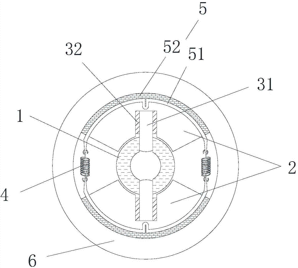
[0023] The present invention provides a clutch, which includes: a clutch cover 6; a hub 1, which is coaxially arranged with the clutch cover 6 and is rotatably arranged in the clutch cover 6; and two flywheels 2 , the two flywheels 2 are attached to the outer peripheral surface of the hub 1 at intervals along the circumferential direction of the hub 1 and can rotate with the hub 1. The circumferential position of the flywheel 2 relative to the hub 1 does not move, and the radial position of the flywheel 2 relative to the hub 1 can be adjusted, and a friction plate 5 is fixedly connected to the outer peripheral surface of each flywheel 2, and the outer peripheral...


PUM


Abstract

The invention discloses a clutch. The clutch comprises a clutch cover (6), a hub (1) and two fly wheels (2), wherein the hub (1) and the clutch cover (6) are coaxially arranged, the hub (1) is rotationally arranged in the clutch cover (6), and the fly wheels (2) are fitted to the outer circumference surface of the hub (1) at intervals along the circumference direction of the hub (1) and can rotate along with the hub (1). The fly wheels (2) stay still relative to the circumferential position of the hub (1) and can be adjusted relative to the radial position of the hub (1), friction plates (5) are fixedly connected on the outer circumference of the fly wheels (2), and the outer circumferences of the friction plates (5) contact with or are separated from the inner circumference of the clutch cover (6). The clutch is simple in structure and convenient to connect and disconnect.

Description

technical field [0001] The invention relates to a clutch. Background technique [0002] Friction clutch is the most widely used and oldest type of clutch. It is basically composed of four parts: the active part, the driven part, the pressing mechanism and the operating mechanism. The main and driven parts and the pressing mechanism are the basic structure to ensure that the clutch is in the engaged state and can transmit power, while the clutch operating mechanism is mainly a device to separate the clutch. During the separation process, step on the clutch pedal, first eliminate the free gap of the clutch in the free stroke, and then generate a separation gap in the working stroke, and the clutch is separated. During the engagement process, the clutch pedal is gradually released, and the pressure plate moves forward under the action of the compression spring, first to eliminate the separation gap, and to exert sufficient compression force on the pressure plate, driven plate ...

Claims


Application Information

Patent Timeline
IPC IPC(8): F16D43/04
Inventor 董家保苏堤董家兵
Owner 芜湖市中亚汽车制动元件有限公司
Why Eureka
Try Eureka