
Rotating mechanism

A technology of rotating mechanism and rotating shaft, which is applied in the field of sapphire single crystal production, can solve the problems of inconvenient use, large size and high cost, and achieve the effect of simplifying equipment structure, reducing space size and no jamming phenomenon

Inactive Publication Date: 2015-01-14
上海朗兆机电设备有限公司
View PDF6 Cites 0 Cited by
  • Summary
  • Abstract
  • Description
  • Claims
  • Application Information

AI Technical Summary

Problems solved by technology

The rotating shaft is installed on the side of the column through the supporting seat, which cannot realize large-angle rotation, is not convenient to use, has a relatively complicated structure, large equipment size, and high cost

Method used


Image

  • Rotating mechanism

Examples


Embodiment Construction

[0015] The rotating mechanism of the present invention will be described in further detail below in conjunction with the accompanying drawings.

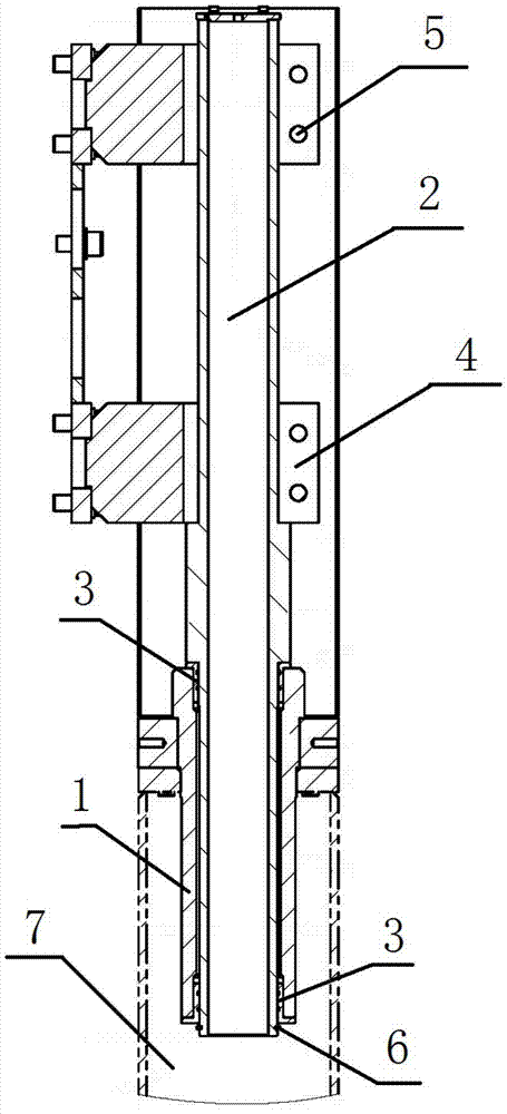
[0016] like figure 1 As shown, the rotating mechanism of the present invention includes: a base 1 in the shape of a through cylinder, and one end of the base 1 is inserted into the column 7 . Insert sliding bushings 3 into the openings at both ends of the base 1 respectively, and apply a small amount of grease in the semicircular annular oil groove (not shown in the figure) of the sliding bushing 3 . Then the rotating shaft 2 is installed into two sliding bushes 3 and runs through the entire base 1 . At the same time, a stop ring 6 is provided at the end of one end of the rotating shaft 2 inserted into the column 7 . At this time, the base 1 and the bush 3 on it can ensure that the rotation shaft 2 rotates smoothly without jamming. And have enough resistance to deformation.

[0017] Then. Install the support 4 on the upper part ...


PUM


Abstract

The invention provides a rotating mechanism. The rotating mechanism comprises a base, a rotating shaft and a supporting seat, wherein the base is a penetrating column and one end of the base is inserted into an upright column; the rotating shaft penetrates through the base and the two ends of the rotating shaft extend out of the two ends of the base, respectively; the supporting seat is arranged on the upper part of the rotating shaft by use of a screw. Bushes are circularly connected with the inner walls of the upper and lower ends of the base. Oil grooves are formed in the bushes. The oil grooves are semicircular. A retainer ring is arranged on the tail end of the end, inserted into the upright column, of the rotating shaft. After the rotating shaft of the rotating mechanism is mounted on the base, smooth and steady rotation of the rotating shaft is guaranteed by use of the base and the bushes on the bases and jamming is avoided. Besides, the rotating mechanism has sufficient deformation resisting capability; next, the rotating shaft is fixedly arranged on the upper part of the upright column and a moving mechanism is mounted and connected to the rotating shaft by use of the supporting seat, so that large-angle rotation can be realized; furthermore, the structure of a device can be simplified, the spatial size of the device can be reduced and the device can be further minimized and reduced in weight.

Description

technical field [0001] The invention relates to the field of sapphire single crystal production, in particular to a rotating mechanism suitable for a sapphire single crystal furnace. Background technique [0002] The rotary mechanism is a common motion mechanism on machinery and equipment, and it has various forms such as column type and disc type. The original rotating mechanism is to fix the rotating shaft on the side of the column with the support seat, and then the moving mechanism is installed on the rotating shaft to make the moving mechanism rotate around the shaft. The rotating shaft is installed on the side of the column through the support seat, which cannot realize large-angle rotation, is not convenient to use, has a relatively complicated structure, large equipment size, and high cost. Contents of the invention [0003] The invention provides a rotating mechanism capable of realizing a large-angle rotation of a moving mechanism around a rotating shaft. [00...

Claims


Application Information

Patent Timeline
Patent Type & Authority Applications(China)
IPC IPC(8): C30B29/20C30B35/00
CPCC30B29/20C30B35/00
Inventor 宋奇
Owner 上海朗兆机电设备有限公司
Learn More