
Plug body for beverage containers

A beverage and container technology, which is applied in the field of plugs for beverage containers, can solve problems such as inability to operate automatically and poor operability, and achieve the effects of preventing misoperation and reducing the number of parts

Active Publication Date: 2015-01-14
THERMOS CHINA HOUSEWARES +1
View PDF9 Cites 10 Cited by
  • Summary
  • Abstract
  • Description
  • Claims
  • Application Information

AI Technical Summary

Problems solved by technology

The locking member keeps the lid closed in a rotatable manner, but unlike the button, it cannot automatically operate during the closing action of the lid, so there is a problem of poor operability.

Method used


Image

  • Plug body for beverage containers
  • Plug body for beverage containers
  • Plug body for beverage containers

Examples


no. 1 approach

[0065] Below, use Figure 1 to Figure 27 The plug body of the first embodiment of the present invention will be described.

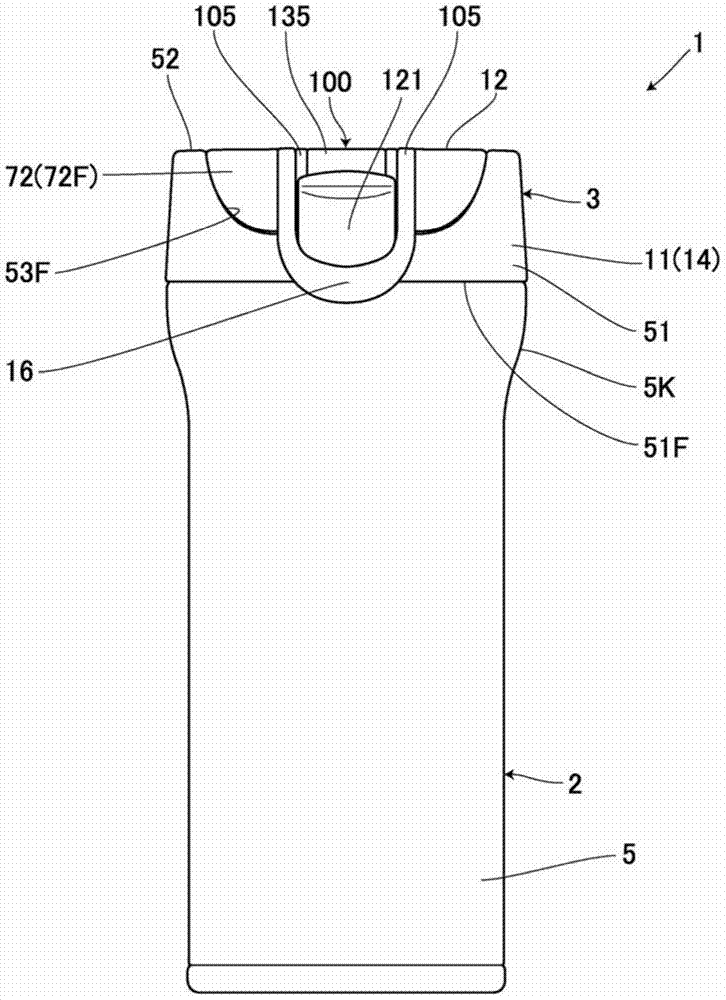
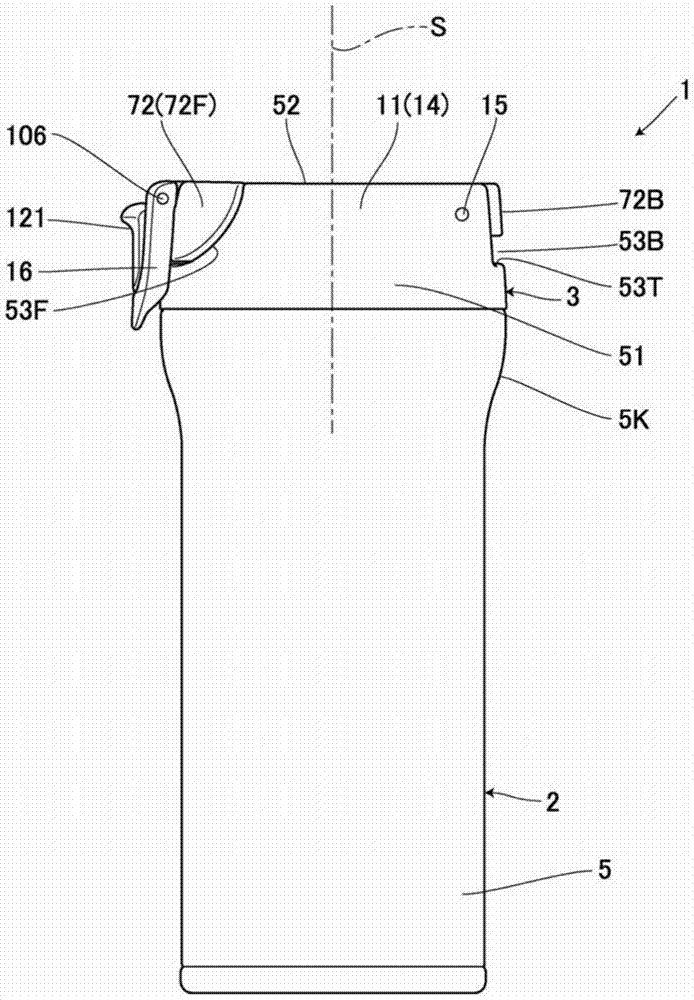
[0066] The plug body of this embodiment is used, for example, in Figure 1 ~ Figure 3 Shown is a container 1 for beverages. The beverage container 1 is composed of a metal container body 2 and a synthetic resin plug 3 .

[0067] The above-mentioned container body 2 has an inner cylinder 4 and an outer cylinder 5 integrally joined at the edge of an opening end 2A as an upper opening, and a heat insulating layer 6 that forms a space between the inner cylinder 4 and the outer cylinder 5 into a vacuum. Double layer insulation construction.

[0068] For example Figure 7 As shown, a head 7 is provided on the opening end 2A side of the container main body 2 . In the head portion 7, both the inner cylinder 4 and the outer cylinder 5 are formed to have larger diameters than the lower portion. In particular, an enlarged portion 5K that expands conically tow...

no. 2 approach

[0232] Figure 28 It is a schematic diagram showing the plug body of the second embodiment of the present invention. The same reference numerals are assigned to the same parts as those in Embodiment 1 described above, and detailed description thereof will be omitted.

[0233] In the present embodiment, a storage portion 85 is provided in the plug body hinge portion 82 , and a slide member 86 having a jig protrusion 90 is provided in the storage portion 85 .

[0234] In this embodiment, the same operations and effects as those of the above-mentioned first embodiment are exerted.

no. 3 approach

[0236] Figure 29 It is a schematic diagram showing the plug body of the third embodiment of the present invention. The same reference numerals are assigned to the same parts as those in the above-mentioned respective embodiments, and detailed description thereof will be omitted.

[0237] In this embodiment, a recess 91 serving as a clip receiving portion is provided on the outer end surface of the slide member 86 , and a clip protrusion 90 is provided on the inner surface of the inner wall portion 57 of the above-mentioned plug body hinge portion 82 corresponding to the recess 91 .

[0238] In this embodiment, the same operations and effects as those of the above-mentioned first embodiment are exerted.


PUM


Abstract

The present invention provides a plug body for beverage containers, wherein a locking mechanism for minimizing a locking part to prevent the occurrence of misoperations is provided. The vertical wall of a cover body is provided with a chimeric shaft. The outer surface of the vertical wall supports the locking part through the shaft bearing effect of the chimeric shaft. The locking part comprises a left arm part, a right arm part and a connecting part. The inner sides of the arm parts of the locking part are provided with a locking crimp part (113). The inner sides of the arm parts are also provided with a locking crimp receiving part. If the locking part is rotated towards the inverse-hinging direction, the locking crimp part is crimped onto the locking crimp receiving part to enable the elastic deformation of the upper part of the locking part in an opening manner. When the cover body is closed, the locking part is in contact with the hook part of a plug body to be rotated. Therefore, the plug body is clamped by the locking part through resetting the hook part of the plug body.

Description

technical field [0001] The present invention relates to a plug for a beverage container provided with a locking mechanism for locking a lid. Background technique [0002] Conventionally, in the plug body of the container for beverages, various methods which restrict the rotation of a lid body by a lock mechanism are proposed (patent documents 1-6). [0003] In the plugs disclosed in Patent Documents 1 to 6, the closed state is maintained by a button. The button always urges the lid in a direction to keep it closed, and the lid is opened by pushing the button. However, since a predetermined pushing gap is required to push the button, miniaturization is difficult. [0004] In addition, in the plug disclosed in Patent Document 1, after the lid is kept closed by the button, the push operation of the button is blocked by covering the front surface operation portion of the button with a sliding member that slides in the vertical direction. Although the pushing operation is hind...

Claims


Application Information

Patent Timeline
Patent Type & Authority Applications(China)
IPC IPC(8): B65D47/08
CPCB65D47/0876B65D47/0804B65D47/121B65D51/18B65D85/72
Inventor 仓部泰宏松山真杜宏梁
Owner THERMOS CHINA HOUSEWARES
Learn More