Method and apparatus for placing or excavating cavities in mountains

A cavity and equipment technology, applied in mining equipment, welding equipment, metal processing equipment, etc., can solve problems such as equipment failure to be implemented, and achieve the effect of avoiding overheating

Active Publication Date: 2017-06-30
约瑟夫·格罗特多斯特
View PDF1 Cites 0 Cited by
  • Summary
  • Abstract
  • Description
  • Claims
  • Application Information

AI Technical Summary

Problems solved by technology

[0003] As far as can be ascertained, the aforesaid method and the attached equipment have not actually been implemented.

Method used


Image

  • Method and apparatus for placing or excavating cavities in mountains
  • Method and apparatus for placing or excavating cavities in mountains
  • Method and apparatus for placing or excavating cavities in mountains

Examples


Embodiment Construction

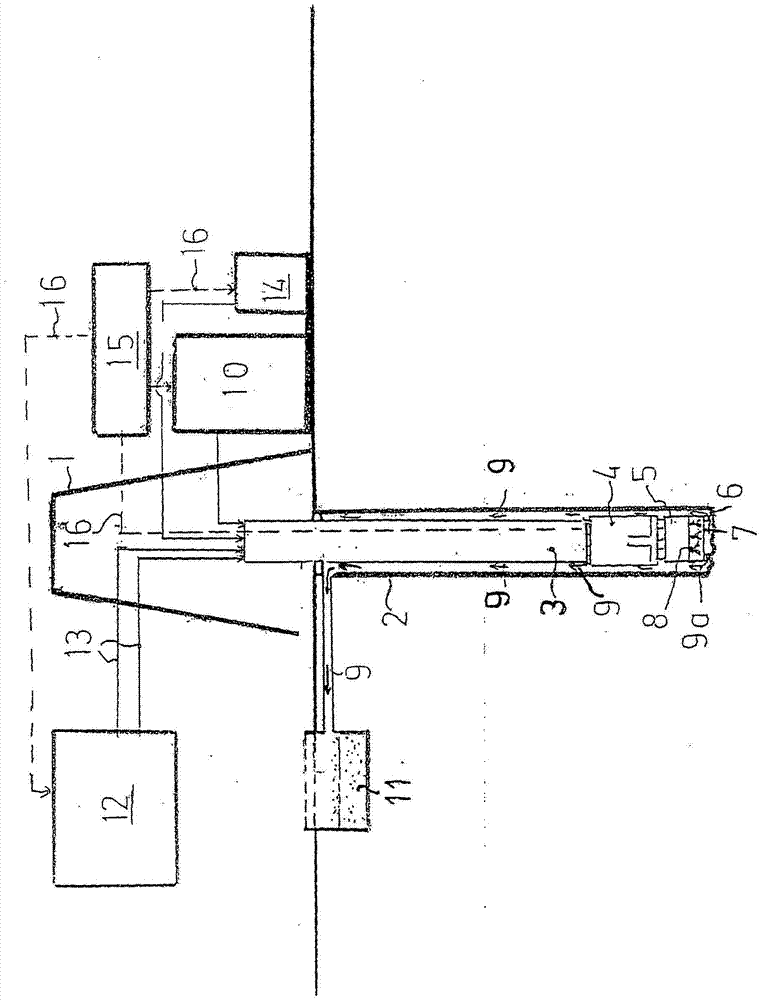
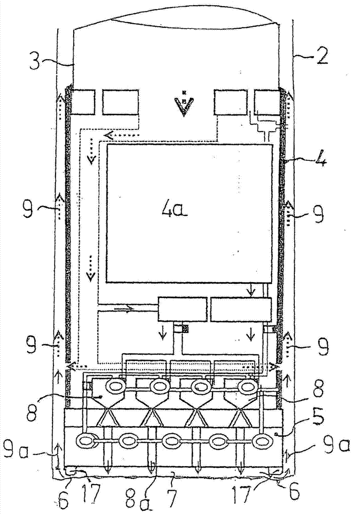
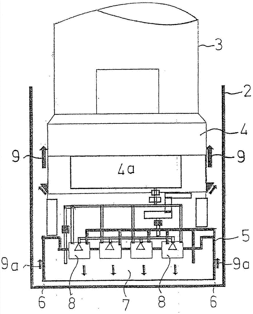
[0031] exist figure 1 In , the excavation platform erected on the surface is marked with reference numeral 1 . This drilling platform 1 is provided with the usual means for inserting a feed and supply device 3 for advancing and supplying a driving head 4 arranged in the cavity 2 to be produced. On its side facing the front of the cavity 2 , the drilling head 4 is provided with a thermal protection cover 5 which covers the front of the cavity 2 up to a gap 6 extending around the periphery and forms a dynamic pressure chamber 7 with the front of the cavity 2 .

[0032] A plurality of electric plasma generators 8 in the form of plasma burners are arranged in or on the heat shield 5 , and their heat melts or vaporizes the rocks located in front of the cavity 2 .

[0033] The rock melted and / or evaporated in front of the cavity 2 is removed from the cavity 2 by means of the gaseous conveying medium indicated by the arrow 9 . This gaseous conveying medium 9 is nitrogen, which is p...


PUM


Abstract

The invention relates to a method for excavating or inserting cavities in mountains, in which method the cavities (2) are melted frontally by means of an electric plasma generator. In order to generate in such a method an energy density sufficient to completely or partially vaporize the existing rock on the front of the cavity (2), the invention proposes that a thermal protection shield (4) is arranged directly on the front of the cavity (2), which heat The protective cover and the front face of the cavity (2) form a dynamic pressure chamber (7), in which the temperature is adjusted to be higher than 2000°C by heating with a plasma generator (8) at a pressure greater than 2 bar. This energy supply is sufficient to melt, completely or partially vaporize and expel the rock located in front of the cavity (2) from the cavity (2).

Description

technical field [0001] The invention relates to a method and a device for inserting or excavating cavities in mountains, in which rocks located on the front of the cavities are thermally melted and removed from the cavities by means of a gaseous conveying medium, wherein at least one electrical A type plasma generator provides the heat required for melting the rock, and the electric type plasma generator is assigned to the driving head (Vortriebskopf), which is located in front of the supply device which can be pushed into the cavity. Cavities in mountains are understood here to mean all kinds of boreholes, boreholes, mines, tunnels, tunnels, chambers, etc. Background technique [0002] Such a method and associated equipment are known from US Pat. No. 3,467,206. In this method known from the prior art, a holder for the plasma burner is provided on the front of the drilling head, which can be rotated around the axis of the cavity and is supported on the front of the cavity b...

Claims


Application Information

Patent Timeline
Patent Type & Authority Patents(China)
IPC IPC(8): E21B7/15
CPCE21B7/15B23K10/00B23K2103/50E21C37/16E21D1/00E21D9/1073E21D13/00
Inventor 约瑟夫·格罗特多斯特
Owner 约瑟夫·格罗特多斯特
Why Eureka
Try Eureka