Rail flaw detection dynamic test device
A dynamic test and rail technology, which is applied in the direction of using sound waves/ultrasonic waves/infrasonic waves to analyze solids, etc., can solve problems such as unfavorable installation of testing equipment, requirements for line length, inconvenient rail replacement, etc., to achieve less human constraints and perfect functions Reliable, Lightweight Effects
- Summary
- Abstract
- Description
- Claims
- Application Information
AI Technical Summary
Problems solved by technology
Method used
Image
Examples
Embodiment 1
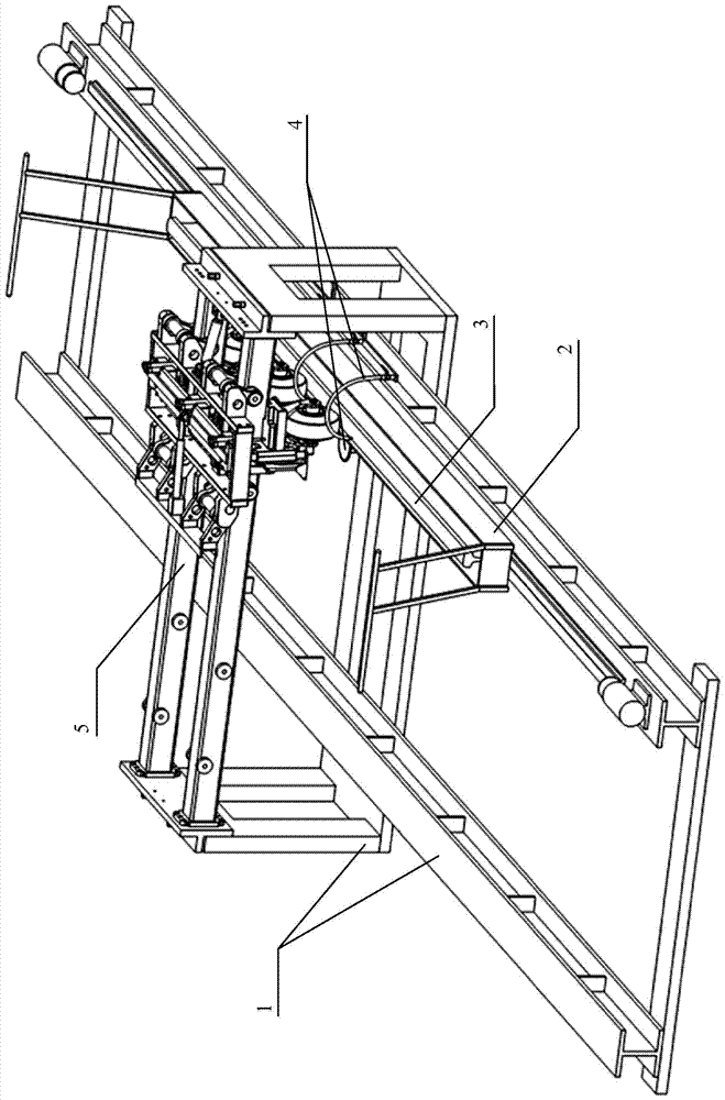
[0051] as attached figure 2 As shown, the specific embodiment of the rail flaw detection dynamic test device of the present invention includes:
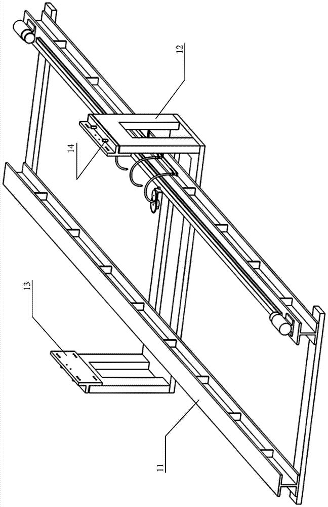
[0052] The support frame 1 for carrying the wheel detection device 5, the wheel detection device 5 is arranged on the upper part of the support frame 1;
[0053] A sliding platform 2 is movably arranged at the bottom of the supporting frame 1 along the length direction of the supporting frame 1, and the sliding platform 2 is located below the detection wheel device 5;
[0054] The rail test block 3 arranged on the sliding platform 2, the rail test block 3 is located under the detection wheel device 5, the rail test block 3 can be driven by the sliding platform 2, along the length direction of the support frame 1, and relative to the detection wheel The device 5 moves, and the rail test block 3 is used to provide various damage simulations of the rail;
[0055] The auxiliary device 4 includes a coupling water injection device 42 , ...
Embodiment 2
[0067] as attached Figure 10 As shown, the specific embodiment of the rail flaw detection dynamic test method based on the device of the present invention may further comprise the steps:
[0068] On the upper part of the supporting frame 1, a wheel detection device 5 is arranged;
[0069] A sliding platform 2 is movably arranged along the length direction at the bottom of the supporting frame 1, and the sliding platform 2 is located below the wheel detection device 5;
[0070] A rail test block 3 is arranged on the sliding platform 2, and the rail test block 3 is located below the detection wheel device 5. The rail test block 3 can be driven by the sliding platform 2, along the length direction of the support frame 1, and relative to the detection wheel device. 5 moving, the rail test block 3 is used to provide various damage simulations of the rail;
[0071] An auxiliary device 4 is provided on the supporting frame 1 , and the auxiliary device 4 includes a coupling water j...
Embodiment 3
[0080] as attached Figure 12 , 13 , 14 and 15, the specific embodiment of the rail test block in the method of the present invention, the rail flaw detection test block is provided with a bolt hole saw kerf for simulating bolt hole cracks on the rail, and a rail waist for simulating the rail waist position defect. The rail test block 3 is formed by any one or several kinds of damages in the transverse hole, the rail head transverse hole for simulating the rail head defect, and the rail bottom sawing for simulating the rail bottom crack. The rail test block 3 described in the specific embodiment of the present invention can provide damage samples that are basically consistent with the dedicated line for simulating various rail damages in ultrasonic non-destructive testing, and comprehensively meet the needs of the actual situation of rail flaw detection.
[0081] The rail test block 3 includes a first test block 31, and the first test block 31 is provided with a bolt hole saw...
PUM
 Abstract
Description
Claims
Application Information
 - Generate Ideas
- Intellectual Property
- Life Sciences
- Materials
- Tech Scout
- Unparalleled Data Quality
- Higher Quality Content
- 60% Fewer Hallucinations
Browse by: Latest US Patents, China's latest patents, Technical Efficacy Thesaurus, Application Domain, Technology Topic, Popular Technical Reports.
© 2025 PatSnap. All rights reserved.Legal|Privacy policy|Modern Slavery Act Transparency Statement|Sitemap|About US| Contact US: help@patsnap.com


