Core bag structure hobbing cutter, and use method as well as application thereof
A technology of hob and core pack, which is applied in the direction of earth drilling, mining equipment, tunnels, etc., can solve the problems of no hob bearing capacity, wear resistance improvement, etc., achieve ingenious design concept, increase bearing capacity, and obvious effect Effect
- Summary
- Abstract
- Description
- Claims
- Application Information
AI Technical Summary
Problems solved by technology
Method used
Image
Examples
Embodiment 1
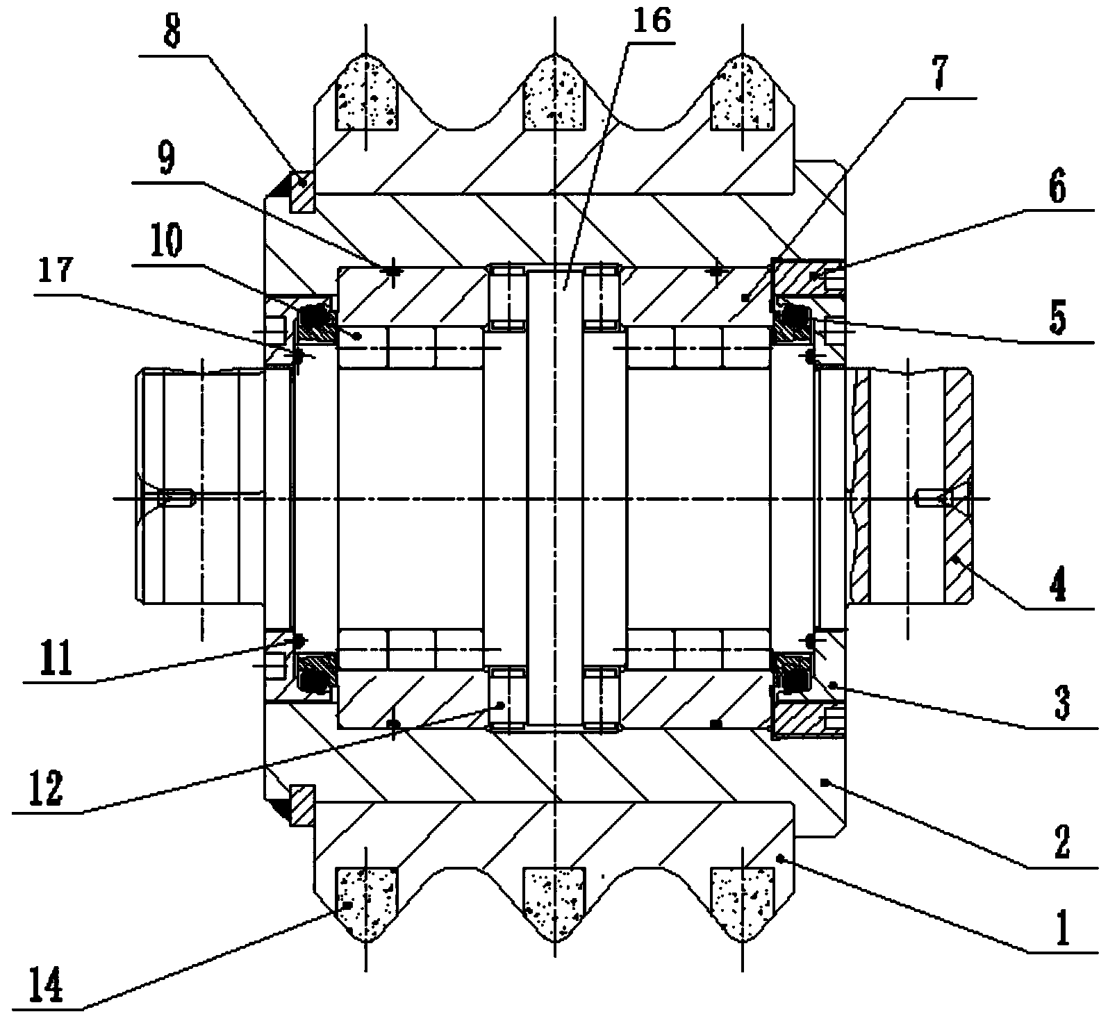
[0026] A hob with a core package structure, comprising a cutter shaft 4, a cutter body 2, a three-edged insert cutter ring 1 and an end cover 3, a shaft shoulder 16 is arranged at the center of the cutter shaft 4, and two sides of the shaft shoulder 16 are symmetrically arranged Step 17, the cutter shaft 4 runs through the cutter body 2, and a thrust bearing 12 and a cylindrical roller bearing are arranged between the cutter shaft 4 and the cutter body 2. The cylindrical roller bearing is composed of a cylindrical roller 10 and a jacket 7. The thrust bearings 12 are arranged respectively, and the cylindrical roller bearings are arranged between the thrust bearings 12 and the steps 17;
[0027] One end of the inside of the cutter body 2 is provided with a boss, one end of the outer side of the cutter body 2 is provided with a boss and the other end is provided with a groove, the groove is provided with a retaining ring 8, and the outside of the cutter body 2 is provided with the...
Embodiment 2
[0031] A core-packed structure hob, the structure is as described in Example 1, the difference is that an O-shaped sealing ring 9 is arranged between the cutter body 2 and the cylindrical roller bearing, and an O-shaped sealing ring 9 is arranged between the end cover 3 and the cutter shaft 4. O-ring 11 is arranged. The added O-ring mainly acts as a seal to prevent oil leakage.
Embodiment 3
[0033] A hob with a core-wrapped structure, the structure of which is as described in Embodiment 1, the difference is that the cutter ring is an integral cutter ring not inlaid with alloy. In the actual operation process, the cutter ring can be set as a single-edged or multi-edged cutter ring according to the actual working environment. A thrust pin 13 is arranged between the cutter body 2 and the lock nut 6, and a thrust pin 15 is arranged between the lock nut and the cutter shaft 4, and the thrust pin can effectively prevent the lock nut and the end cap from loosening.
PUM
 Abstract
Description
Claims
Application Information
 - R&D
- Intellectual Property
- Life Sciences
- Materials
- Tech Scout
- Unparalleled Data Quality
- Higher Quality Content
- 60% Fewer Hallucinations
Browse by: Latest US Patents, China's latest patents, Technical Efficacy Thesaurus, Application Domain, Technology Topic, Popular Technical Reports.
© 2025 PatSnap. All rights reserved.Legal|Privacy policy|Modern Slavery Act Transparency Statement|Sitemap|About US| Contact US: help@patsnap.com


