A kind of oil, mud, water separation device

A separation device and separation tank technology, applied in the field of mud, water separation device and oily mud oil, can solve the problems of large pollution of the environment, waste of water resources, low liquid temperature, etc. Good results

Active Publication Date: 2016-02-03
SHANDONG HYGIYA ENVIRONMENTAL PROTECTION EQUIP
View PDF5 Cites 0 Cited by
  • Summary
  • Abstract
  • Description
  • Claims
  • Application Information

AI Technical Summary

Problems solved by technology

[0002] At present, in the treatment of oilfield drilling waste mud, hauling, recycling and centralized treatment are mostly used. The purified water after treatment is discharged or recharged into the formation, resulting in high freight costs and waste of water resources. In the process of crude oil storage and transportation, oily mud is deposited at the bottom of the tank. It is often used for storage in ponds, which takes up a large area after storage for a long time, and oxidizes and deteriorates. It is difficult to process and recycle after it becomes aged oil, which wastes crude oil resources and pollutes the environment.
In order to solve this problem, the Chinese patented oil, mud and water separation device (ZL201220640557.5) was used to carry out the separation test of oil, mud and water in oily mud. There are many deteriorated and aged oils, low liquid temperature, and poor mud fluidity. The treatment of oily mud is not well considered, resulting in serious blockage of the device and unable to operate. Therefore, the problems of high freight, serious environmental pollution, waste of oil and water resources have not been solved.

Method used


Image

  • A kind of oil, mud, water separation device
  • A kind of oil, mud, water separation device
  • A kind of oil, mud, water separation device

Examples


Embodiment Construction

[0024] The present invention will be further elaborated below in conjunction with the accompanying drawings and embodiments.

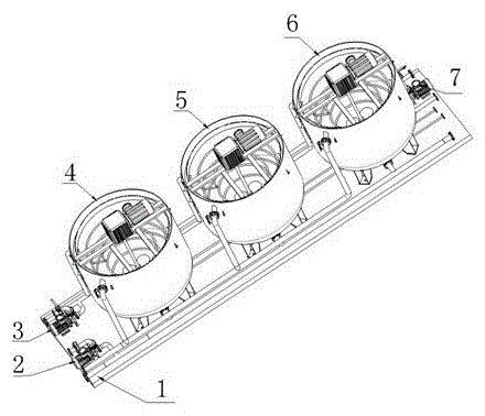
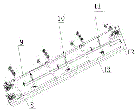
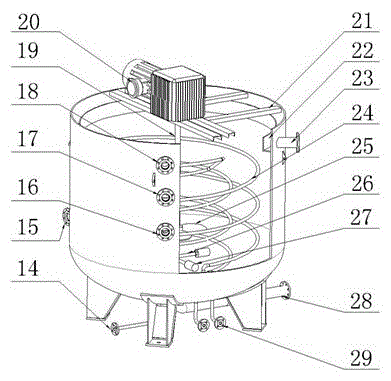
[0025] like Figure 1-9 As shown, an oil, mud and water separation device is characterized in that it includes a base 1, a separation tank, a connecting manifold, a mud discharge pump 2, a water collection pump 3 and a mud lift pump 7, and the base 1 is arranged on the The lower part of the separation device, the connecting manifold mainly includes an oil collection manifold 8, a water collection manifold 9, a liquid inlet manifold 10, an air flotation manifold 11, a heating manifold 12, and a mud discharge manifold 13. The separation Pool includes 1 # Separation pool 4, 2 # Separation pool 5 and 3 # Separation pool 6, and each separation pool is provided with pool steam air flotation nozzle 14, pool body liquid inlet nozzle 15, pool body water outlet nozzle, stirring shaft 19, agitator 20, agitator support 21, oil collection tank 22 , tank body oi...


PUM


Abstract

The invention discloses a novel oil, mud and water separation device. A separation pool is a circular pool, and a stirrer, a steam floatation component, a heating coil and an oil receiving tank are arranged in the inner pool of the separation pool. A pool body oil receiving pipe orifice, a pool body water outlet pipe orifice and a pool body liquid inlet pipe orifice are formed in the pool wall of the separation pool, and a pool body mud discharging pipe orifice, a pool body heating pipe orifice and a pool body steam floatation pipe orifice are formed in the pool bottom of the separation pool. The separation pool is connected with a mud lifting pump, a water receiving pump, a mud discharging pump and heat source equipment through a liquid inlet manifold, an oil receiving manifold, a water outlet manifold, a mud discharging manifold, a heating manifold and a steam floatation manifold. The device integrates water purification and mud removal functions of stewing pyrolysis, stirring scrubbing, gas floatation for oil removal, vortex coagulation and static settling, and realizes integration replacing multiple stages and one machine with multiple purposes. The device is small in size, light in weight, easy in prying mounting, and convenient for a vehicle-carried site for mobile use.

Description

technical field [0001] The invention relates to an oil-containing mud oil, mud and water separation device for treating waste mud from drilling in an oil field and deposition mud in a station oil and water storage tank, in particular to an oil, mud and water separation device. Background technique [0002] At present, in the treatment of waste drilling mud in oilfields, hauling, recycling and centralized treatment are mostly used. The purified water after treatment is discharged or recharged into the formation, which has high freight costs and waste of water resources. In the process of crude oil storage and transportation, oily mud is deposited at the bottom of the tank. Many of them are stored in ponds, which will take up a large area after storage for a long time, and will be oxidized and deteriorated. It is difficult to process and recycle after becoming aged oil, which is a waste of crude oil resources and pollutes the environment. In order to solve this problem, the Ch...

Claims


Application Information

Patent Timeline
Patent Type & Authority Patents(China)
IPC IPC(8): C02F9/10C02F103/10
CPCC02F1/025C02F1/24C02F1/52C02F9/00C02F2103/10C02F2301/08
Inventor 张瑾沈利邵明明刘宝徐红雨
Owner SHANDONG HYGIYA ENVIRONMENTAL PROTECTION EQUIP
Why Eureka
Try Eureka