
High-reliability high-stability multi-rotor-wing unmanned aerial vehicle with quick-dismounting function

A multi-rotor unmanned and reliable technology, applied in aircraft, rotorcraft, transportation and packaging, etc., can solve problems such as easy loosening, low reliability and balance of unmanned aerial vehicles, and weak connection between the arm and the center plate , to achieve the effects of quick disassembly, quick disassembly reliability, improved reliability and high stability

Active Publication Date: 2015-01-07
深圳市科卫泰实业发展有限公司
View PDF7 Cites 18 Cited by
  • Summary
  • Abstract
  • Description
  • Claims
  • Application Information

AI Technical Summary

Problems solved by technology

[0003] For this reason, the purpose of the present invention is to provide a multi-rotor unmanned aerial vehicle with high reliability and high stability of quick disassembly and assembly, so as to solve the problem that the traditional unmanned aerial vehicle arm is not firmly connected with the central disk, and it is easy to loosen, resulting in no The problem of low reliability and balance of human aircraft

Method used


Image

  • High-reliability high-stability multi-rotor-wing unmanned aerial vehicle with quick-dismounting function
  • High-reliability high-stability multi-rotor-wing unmanned aerial vehicle with quick-dismounting function
  • High-reliability high-stability multi-rotor-wing unmanned aerial vehicle with quick-dismounting function

Examples


Embodiment Construction

[0019] In order to make the object, technical solution and advantages of the present invention clearer, the present invention will be further described in detail below in conjunction with the accompanying drawings and embodiments. It should be understood that the specific embodiments described here are only used to explain the present invention, not to limit the present invention.

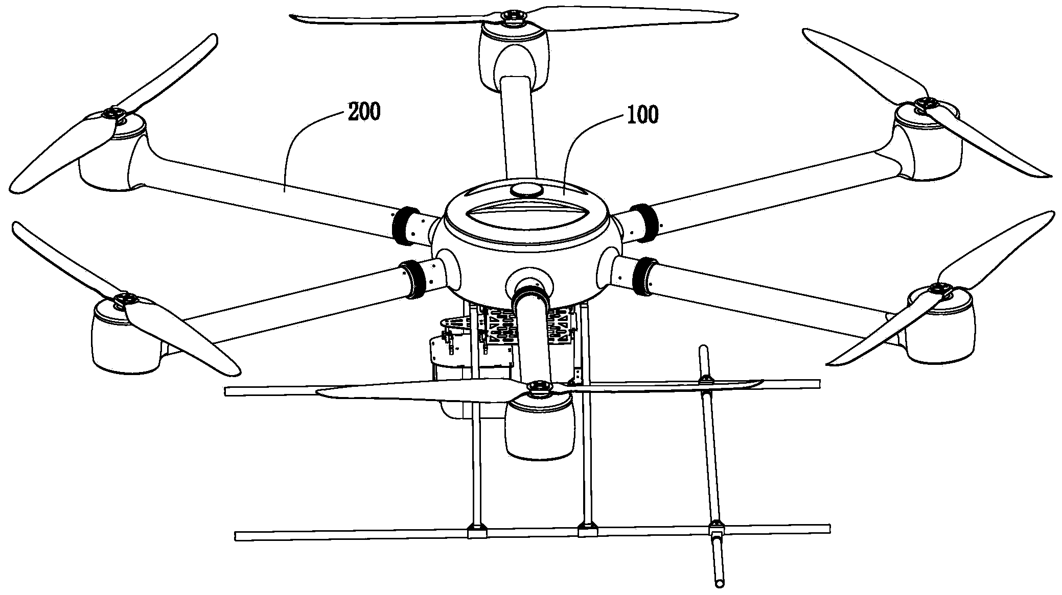
[0020] see figure 1 as shown, figure 1 It is a schematic diagram of the overall effect of the quick disassembly and assembly of the multi-rotor unmanned aerial vehicle of the present invention. The unmanned aerial vehicle described in this embodiment includes a center plate 100 and a plurality of arms 200 installed on the outer circumference of the center plate 100. In this embodiment, there are six arms 200, and the outer circumference of the entire center plate 100 is equally divided into six share.

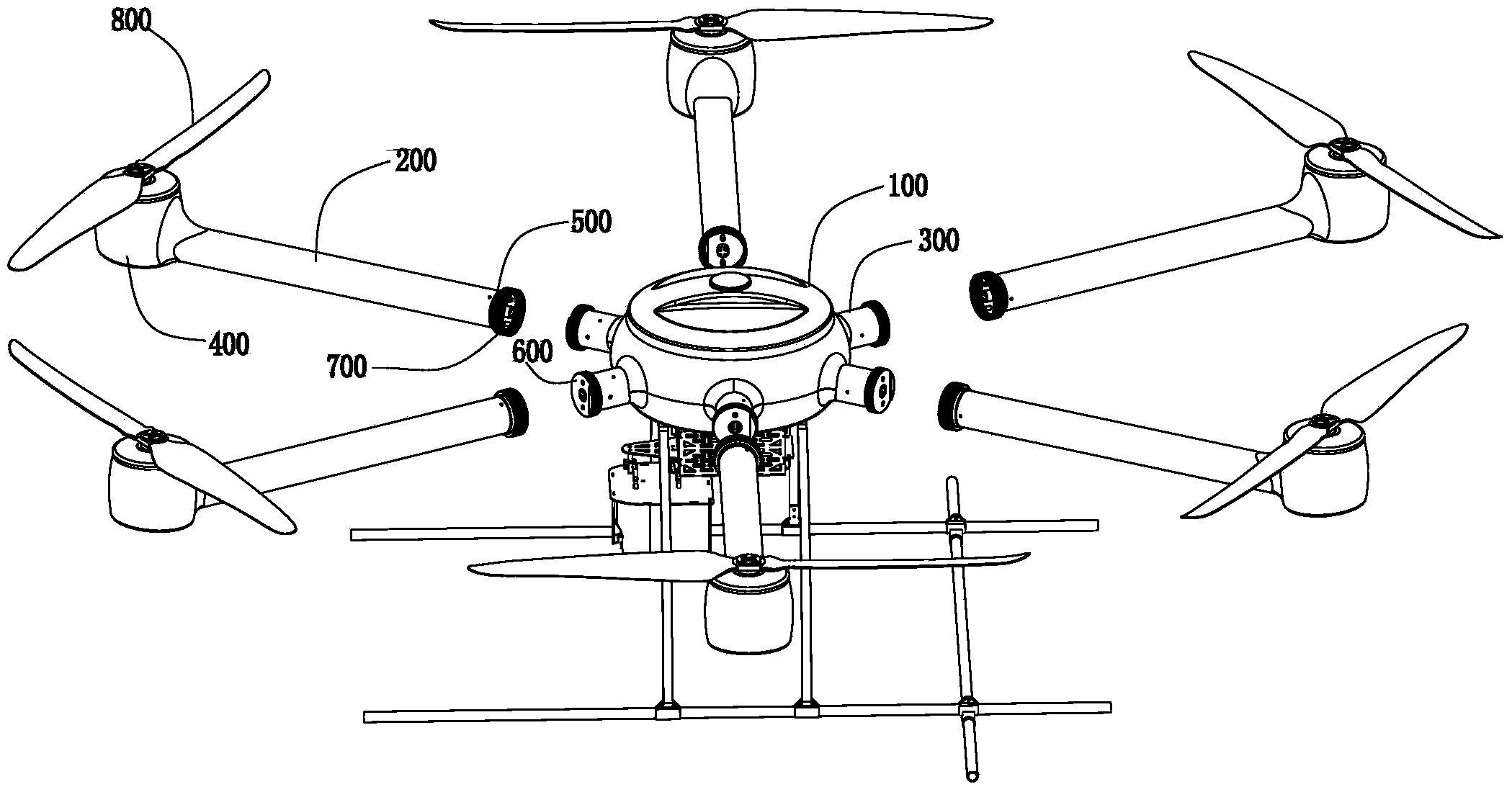
[0021] Such as figure 2 as shown, figure 2 It is a schematic diagram of the separation st...


PUM


Abstract

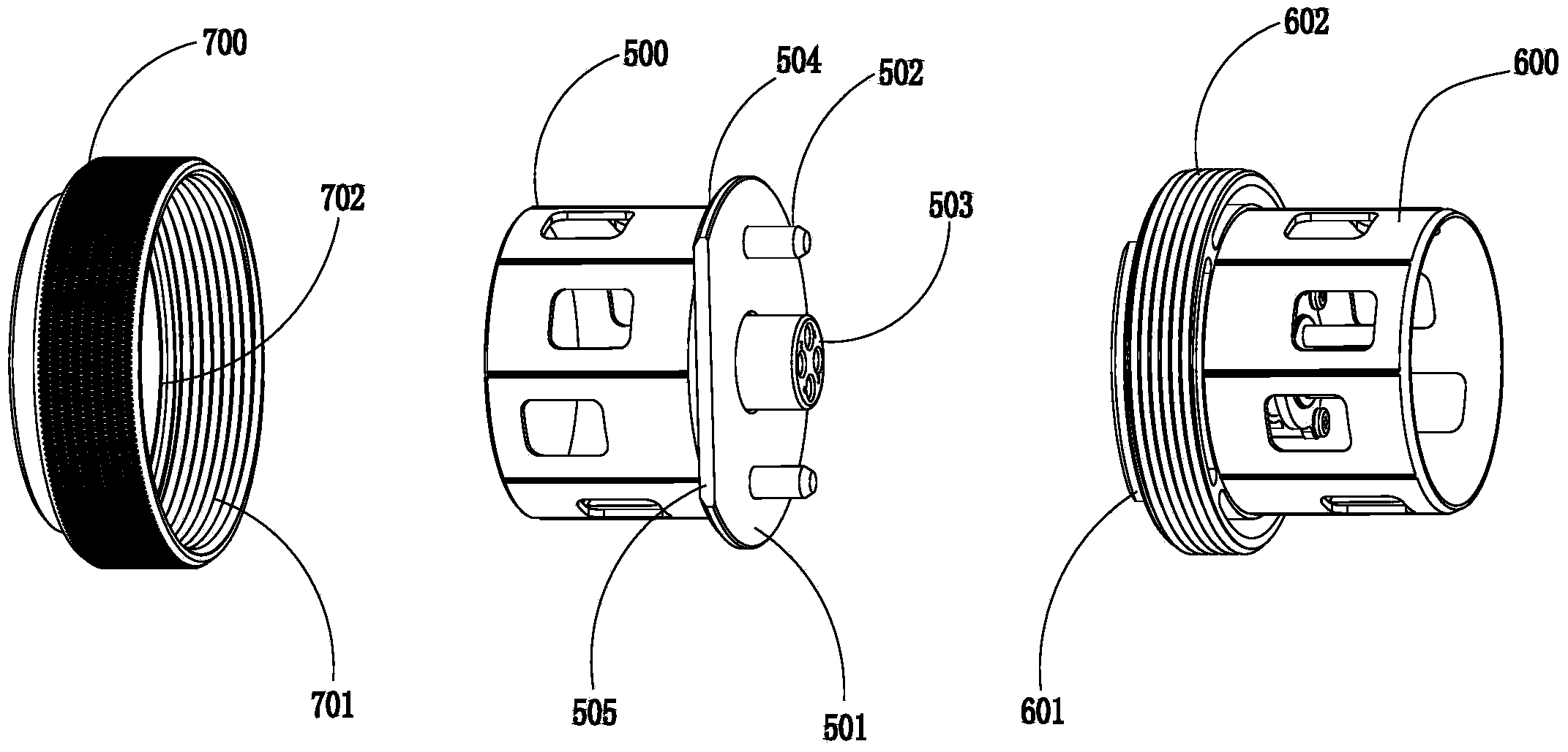
The invention provides a high-reliability high-stability multi-rotor-wing unmanned aerial vehicle with a quick-dismounting function. In order to quickly dismount the unmanned aerial vehicle, the central disc and arms of the unmanned aerial vehicle are split, fan-shaped plates with central angles of more than 180 degrees are arranged on the end surfaces of arm inner parts in arm connecting structures to serve as first limiting convex grooves, fan-shaped plates with central angles of less than 180 degrees are arranged on the end surfaces of central disc inner parts in the arm connecting structures to serve as second limiting convex grooves, and each first limiting convex groove and each second limiting convex groove are clamped together to form a round plate anti-twist structure; meanwhile, in order to prevent twisting of each anti-twist structure, two column positions are added in each connecting structure to reinforce the anti-twist effect, and the arm inner parts are integrally and fixedly connected with the central disc inner parts through thread suites on the outer sides of the formed anti-twist structures, so that the firmness of the unmanned aerial vehicle during flight is guaranteed and the anti-twist function of the arms is improved. The unmanned aerial vehicle has the advantages of simple structure, and has the advantages of quickness for dismounting and convenience for connecting and mounting; especially, the firmness and rigidity of connection are guaranteed, and the flight reliability and stability of the unmanned aerial vehicle are greatly improved.

Description

technical field [0001] The invention relates to a multi-rotor unmanned aerial vehicle, in particular to a multi-rotor unmanned aerial vehicle with high reliability and high stability of quick disassembly and assembly. Background technique [0002] Micro multi-rotor unmanned aerial vehicles with vertical take-off and landing and stable hovering have very broad application prospects in civilian and military fields. Although common micro-miniature unmanned aerial vehicles can take off and land vertically and hover in the air, but due to The fixed connection between the arm and the center plate of a UAV-like UAV adopts ordinary plug or simple screw connection. In the case of high-speed rotating flight of the rotor, especially after long-term use or flight, the connection between the center plate and the arm may become loose or the machine may become loose. The problem of twisting and tilting of the arm causes unbalanced forces on the drone to cause vibration and shaking. As a r...

Claims


Application Information

Patent Timeline
Patent Type & Authority Applications(China)
IPC IPC(8): B64C27/08B64C27/02
Inventor 不公告发明人
Owner 深圳市科卫泰实业发展有限公司
Learn More