
Oil pump test system and its test method

A test system and test method technology, applied in the field of injection molding machines, can solve problems such as uneven quality, long test cycle, and inability to guarantee product quality.

Active Publication Date: 2016-11-23
佛山市顺德区震德塑料机械有限公司
View PDF6 Cites 0 Cited by
  • Summary
  • Abstract
  • Description
  • Claims
  • Application Information

AI Technical Summary

Problems solved by technology

[0002] The working process of an injection molding machine is generally divided into stages such as mold clamping, injection, plasticization, pressure holding, cooling, mold opening and ejection. Different stages require hydraulic systems to provide different pressure flows, so hydraulic oil generally undergoes pressurization. , the cyclic process of pressure holding and pressure relief, with the continuous deepening of energy conservation and environmental protection awareness, people put forward higher and higher requirements for the energy consumption and control accuracy of traditional injection molding machines, which require high control accuracy, good stability and low noise Wait, this has quite high requirements for oil pumps. However, there are many brands of oil pumps on the market, and the quality varies. Many oil pump demanders have to solve the problem. If the oil pump is installed on the machine and carried out follow-up test during work, not only the test period is long, but also the product quality cannot be guaranteed.

Method used


Image

  • Oil pump test system and its test method
  • Oil pump test system and its test method

Examples


Embodiment Construction

[0022] The present invention will be further described below in conjunction with the accompanying drawings and embodiments.

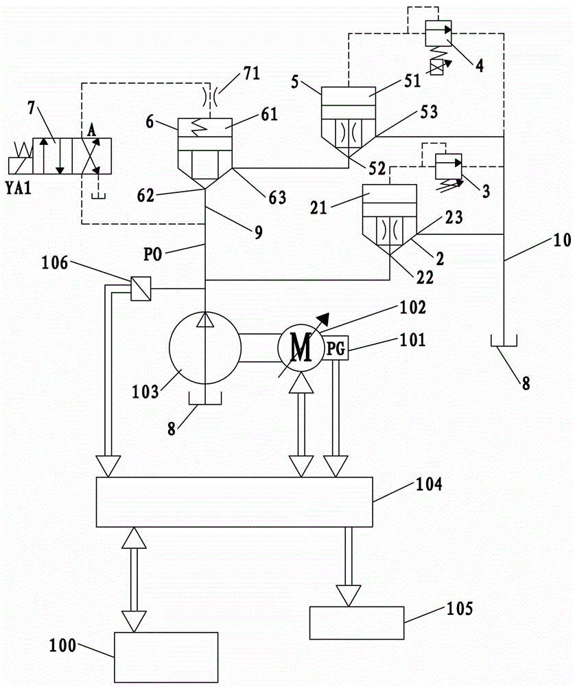
[0023] see figure 1 As shown, an oil pump test system includes a main controller 100, a servo motor 102 for driving the oil pump 103 under test, a servo control assembly for controlling the servo motor 102, a proportional relief valve 4, and a second relief valve 3 And the main oil circuit PO connected to the output port of the tested oil pump 103 is characterized in that it also includes a main test oil circuit for simulating the operation of the oil pump in the injection molding machine. The main test oil route is the cartridge valve A6 and the cartridge valve B5 , cartridge valve C2, directional valve 7, oil inlet pipeline 9 and oil return pipeline 10, cartridge valve A6 and cartridge valve B5 are connected in series between oil inlet pipeline 9 and oil return pipeline 10, and cartridge valve C2 is connected to Between the oil inlet pipeline 9 and t...


PUM


Abstract

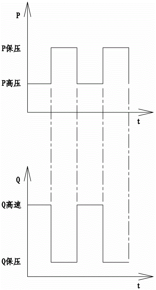
The invention relates to an oil pump test system and a test method using the same. The oil pump test system comprises a main controller, a servo motor for driving a detected oil pump, a servo control assembly for controlling the servo motor, a proportional overflow valve, a second overflow valve and a main oil way connected to an outlet of the detected oil pump and also comprises a main test oil way for simulation of work of the oil pump in an injection machine. The main test oil way comprises a cartridge inserted valve A, a cartridge inserted valve B, a cartridge inserted valve C, a direction valve, an oil inlet pipe and an oil return pipe. The proportional overflow valve is used for controlling return oil pressure. The cartridge inserted valve C and the second overflow valve form a main safety pressure controller of a main oil way. An oil outlet of the second overflow valve is connected to an oil tank by the oil return pipe. Oil supplied by the tested oil pump goes through the cartridge inserted valves and then return the oil tank so that a test is finished. The proportional overflow valve controls the returned oil pressure so that pressure pulsation, high-speed high-pressure performance, pressure maintaining performance, noise, fatigue and internal leakage tests on the oil pump are realized.

Description

technical field [0001] The invention relates to the technical field of injection molding machines, in particular to an oil pump test system and a test method thereof. Background technique [0002] The working process of an injection molding machine is generally divided into stages such as mold clamping, injection, plasticization, pressure holding, cooling, mold opening and ejection. Different stages require hydraulic systems to provide different pressure flows, so hydraulic oil generally undergoes pressurization. , the cyclic process of pressure holding and pressure relief, with the continuous deepening of energy conservation and environmental protection awareness, people put forward higher and higher requirements for the energy consumption and control accuracy of traditional injection molding machines, which require high control accuracy, good stability and low noise Wait, this has quite high requirements for oil pumps. However, there are many brands of oil pumps on the mar...

Claims


Application Information

Patent Timeline
Patent Type & Authority Patents(China)
IPC IPC(8): B29C45/76
CPCB29C45/82B29C2945/7601B29C2945/76214B29C2945/7623B29C2945/76247
Inventor 蒋志坚张贤宝胡军廖伟阳陈伟
Owner 佛山市顺德区震德塑料机械有限公司
Learn More