
Charging apparatus, power supply method, terminal device and charging method

A technology of terminal equipment and charging equipment, which is applied in the direction of secondary battery charging/discharging, battery circuit devices, current collectors, etc., can solve problems such as difficulty in compatibility, burning of terminal equipment, unfavorable environmental protection, etc., and achieve the effect of saving social resources

Inactive Publication Date: 2014-12-31
HUAWEI DEVICE CO LTD
View PDF5 Cites 16 Cited by
  • Summary
  • Abstract
  • Description
  • Claims
  • Application Information

AI Technical Summary

Problems solved by technology

However, due to the different voltage standards of different brands or types of terminal equipment, there are certain differences in the voltage or current required for the operation of each terminal equipment, so that the compatibility between the respective chargers corresponding to each terminal equipment still has a certain degree of difficulty. Difficulty
[0006] Therefore, in the prior art, it is difficult to achieve compatibility between chargers corresponding to different brands or types of terminal equipment, and each user needs to have multiple chargers to charge each terminal equipment, which is neither conducive to environmental protection nor utilization. user use
Moreover, when users use the charger, they need to carefully identify which charger corresponds to the terminal device that needs to be charged. If they accidentally use the wrong charger, it is likely that the terminal device will be burned due to the mismatch between the output voltage and current, and the terminal will be shortened. equipment lifespan

Method used


Image

  • Charging apparatus, power supply method, terminal device and charging method
  • Charging apparatus, power supply method, terminal device and charging method
  • Charging apparatus, power supply method, terminal device and charging method

Examples


Embodiment Construction

[0056] The following describes the technical solutions in the embodiments of the present invention clearly and completely with reference to the accompanying drawings in the embodiments of the present invention. Obviously, the described embodiments are only a part of the embodiments of the present invention, rather than all the embodiments. Based on the embodiments of the present invention, all other embodiments obtained by those of ordinary skill in the art without creative work shall fall within the protection scope of the present invention.

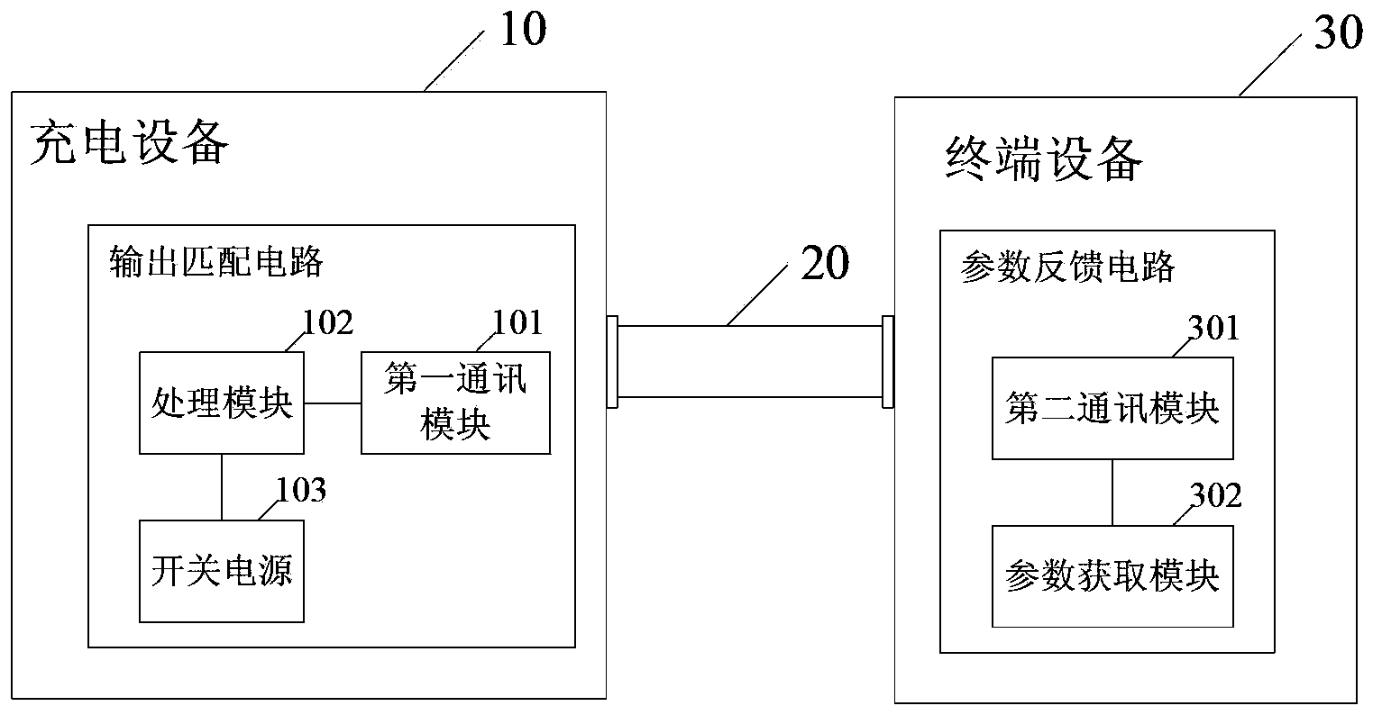
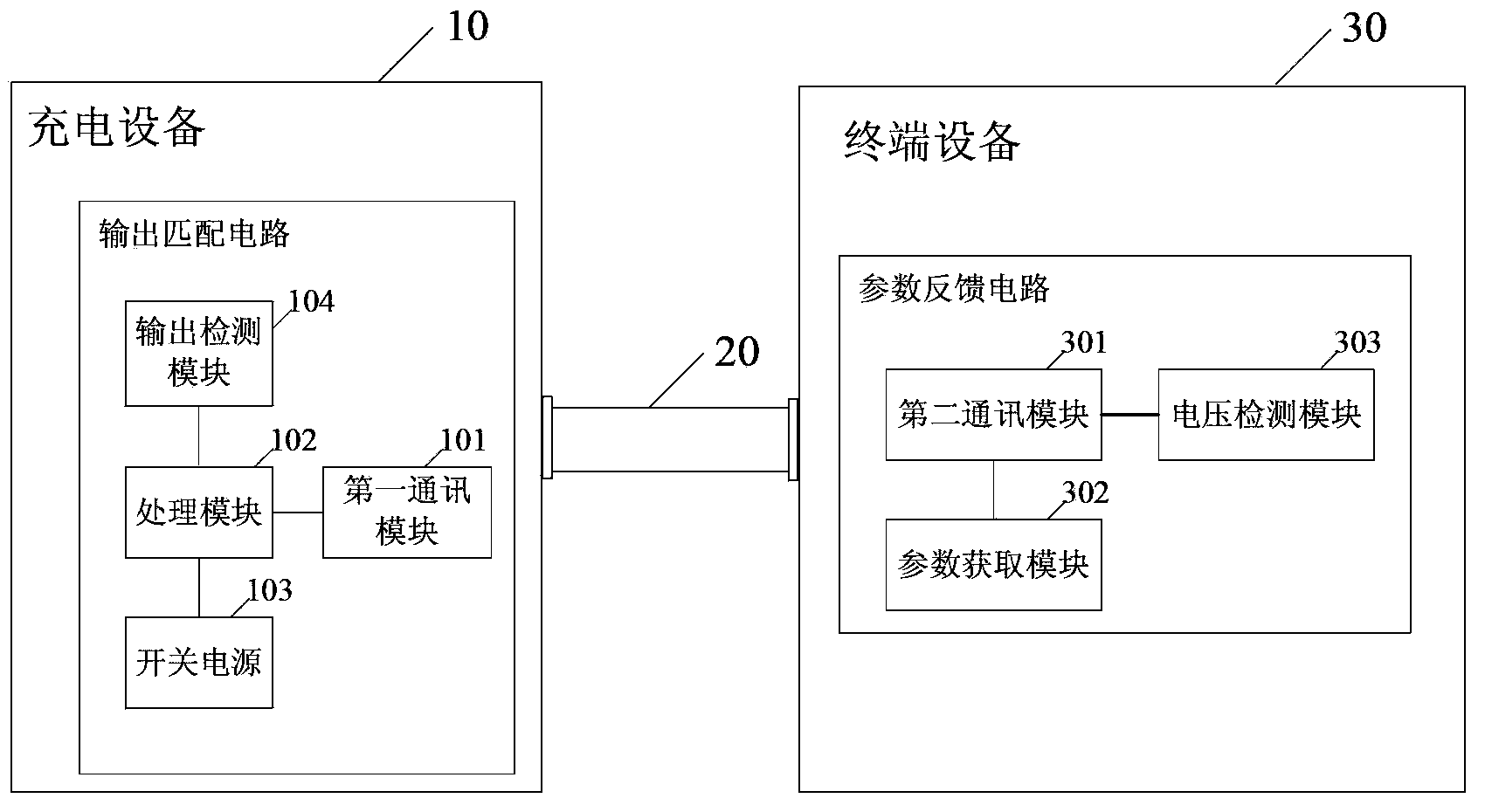
[0057] The embodiment of the present invention provides a charging device and a power supply method, a terminal device and a charging method, which can provide matching operating voltages and currents for terminal devices of different brands and types, realize the universalization of charging devices, and are not only beneficial to environmental protection, but also Can enhance user experience.

[0058] Reference figure 2 , Is a structural ...


PUM


Abstract

The embodiment of the invention discloses a charging apparatus. An output matching circuit of the charging apparatus includes the following components of: a first communication module which establishes a communication connection with a communication module of a terminal device, and receives a parameter configuration request message which is sent by the terminal device and includes a rated parameter value of the terminal device, and sends the parameter configuration request message to a processing module; the processing module which sets an output value matched with the terminal device according to the rated parameter value; and a switching power source which is used for adjusting the output of the charging apparatus so as to make the output equal to the output value matched with the terminal device. The embodiment of the invention also provides a power supply method, a terminal device and a charging method. With the charging apparatus, power supply method, terminal device and charging method of the embodiment of the invention, matched working voltage and current can be provided for different brands and categories of terminal devices, and the universalization of the charging apparatus can be realized, and environmental protection can be benefitted.

Description

Technical field [0001] The present invention relates to the technical field of terminal power supply, in particular to a charging device and a power supply method, a terminal device and a charging method. Background technique [0002] Terminal devices generally use rechargeable batteries to provide power. Rechargeable batteries need to be replenished regularly, and the power required for charging is generally converted from 220V alternating current by the charger. [0003] Such as figure 1 Shown is the working principle diagram of a prior art charger. In the prior art, the charger 1a converts 220V alternating current into 5V direct current voltage, and outputs it to the terminal device 3a through the USB connection line 2a to charge the rechargeable battery of the terminal device 3a. [0004] With the continuous updating of terminal equipment types and the increasing popularity of terminal equipment, the generalization trend of chargers has received more and more attention. For ex...

Claims


Application Information

Patent Timeline
IPC IPC(8): H02J7/00H01M10/44
CPCY02E60/10
Inventor 李长琦
Owner HUAWEI DEVICE CO LTD
Learn More