
Magnetron Die and Magnetron

A magnetron and tube core technology, applied in the field of magnetron, can solve the problems that microwave ovens cannot pass electromagnetic compatibility related tests, and do not fully consider the suppression of magnetron noise, so as to increase the frequency interval, suppress noise, and improve Effect of Electromagnetic Compatibility

Active Publication Date: 2016-06-08
GUANGDONG WITOL VACUUM ELECTRONICS MFR
View PDF6 Cites 0 Cited by
  • Summary
  • Abstract
  • Description
  • Claims
  • Application Information

AI Technical Summary

Problems solved by technology

For example, for a magnetron with ten blades 12 "of anode parts, the distance from the bottom surface of the upper magnetic pole 31" to the top end surface of the blade 12" and the distance from the bottom surface of the lower magnetic pole 32" to the bottom end surface of the blade 12" are the same. 1.3~1.5mm, and the outer diameter of the bottom surface of the upper magnetic pole 31" and the bottom surface outer diameter of the lower magnetic pole 32" are both 9~12mm. The magnetron with this structure only considers the improvement of the output efficiency of the magnetron. However, the suppression of magnetron noise is not fully considered, so unnecessary noise is generated in the frequency band and high-order harmonics adjacent to the fundamental wave (2400-2500MHz), resulting in microwave ovens using such high-efficiency magnetrons being unable to pass through electromagnetic waves. Compatible related tests

Method used

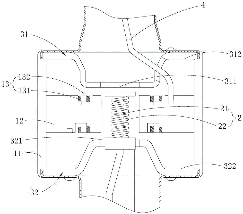
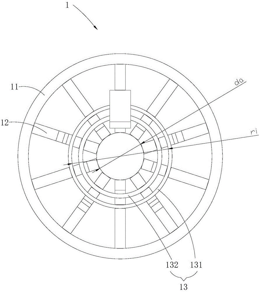
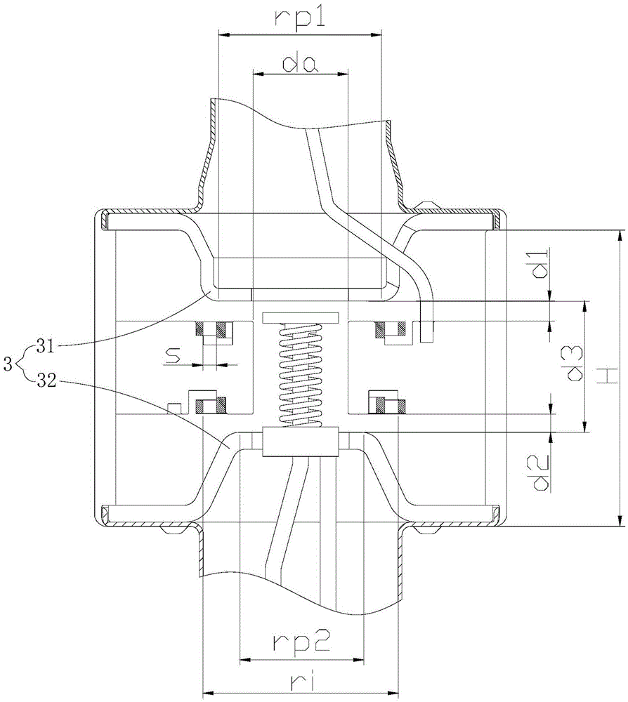

Image

  • Magnetron Die and Magnetron
  • Magnetron Die and Magnetron
  • Magnetron Die and Magnetron

Examples


Embodiment Construction

[0019] In order to make the object, technical solution and advantages of the present invention clearer, the present invention will be further described in detail below in conjunction with the accompanying drawings and embodiments. It should be understood that the specific embodiments described here are only used to explain the present invention, not to limit the present invention.

[0020] Such as Figure 1 ~ Figure 3 As shown, the magnetron tube core provided by the embodiment of the present invention includes an anode part 1, a cathode part 2 and a magnetic pole part 3. The cathode part 2 is inserted from the bottom end of the anode part 1 along the longitudinal axis direction of the anode part 1. In the anode part 1 , the magnetic pole part 3 includes an upper magnetic pole 31 and a lower magnetic pole 32 , and the upper magnetic pole 31 and the lower magnetic pole 32 are asymmetrically arranged at the top and bottom of the anode part 1 . According to the distribution law ...


PUM


Abstract

The invention is applicable to the technical field of magnetron structure, and discloses a magnetron tube core, which includes an anode part, a cathode part and a magnetic pole part, and the cathode part is inserted into the In the anode part, the magnetic pole part includes an upper magnetic pole and a lower magnetic pole, and the upper magnetic pole and the lower magnetic pole are arranged asymmetrically on the top and bottom ends of the anode part. Through the asymmetric form of the upper magnetic pole and the lower magnetic pole at the top and bottom of the anode part, the distribution of the magnetic field lines of the magnetic field can be effectively improved, thereby effectively increasing the frequency interval between the working mode and the adjacent interference mode, thereby effectively improving the magnetic control. The electromagnetic compatibility of the tube effectively suppresses the unnecessary noise emitted by the magnetron tube core when it is working. The present invention also provides a magnetron, which includes a casing, a heat dissipation component arranged in the casing, and the above-mentioned magnetron tube core, and the heat dissipation component is arranged between the outer wall of the anode part and the inner wall of the casing.

Description

technical field [0001] The invention belongs to the technical field of magnetron structures, and in particular relates to a magnetron tube core and a magnetron with the magnetron tube core. Background technique [0002] Magnetron is a vacuum electron tube that generates microwaves. Because of its high oscillation efficiency and high microwave output power, it is widely used as a microwave source for microwave applications such as household microwave ovens and industrial microwave heating equipment. [0003] Such as Figure 4 As shown, the existing magnetron includes a shell 8 ", a tube core (not labeled) located in the shell 8 ", an input power supply 7 "set at the bottom of the shell 8 ", and an inner wall of the shell 8 " and The heat dissipation part 6" between the outer walls of the tube core, wherein the tube core includes an anode part (not numbered in the figure), a cathode part 2", an output part 5" and a magnetic pole part (not numbered in the figure) forming a magn...

Claims


Application Information

Patent Timeline
Patent Type & Authority Patents(China)
IPC IPC(8): H01J23/02H01J23/11H01J25/50
Inventor 王贤友钟立松王彩育刘志勇施志雄
Owner GUANGDONG WITOL VACUUM ELECTRONICS MFR
Learn More