LED working mode control apparatus
A technology of control device and working mode, applied in lighting device, electric lamp circuit arrangement, light source and other directions, can solve the problems of luminous brightness, power improvement limitation, low utilization rate, etc. cost effect
- Summary
- Abstract
- Description
- Claims
- Application Information
AI Technical Summary
Problems solved by technology
Method used
Image
Examples
Embodiment 1
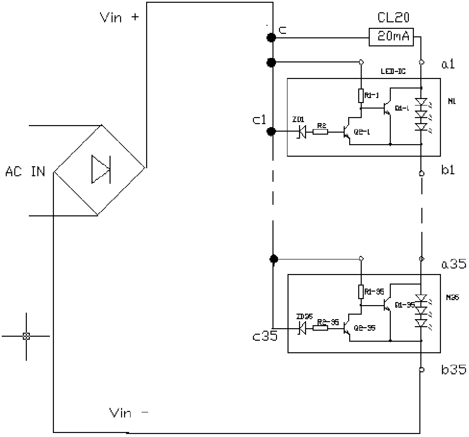
[0069] Such as figure 1 As shown: the connection relationship is as follows:
[0070] 1. The rectifier circuit is a bridge rectifier. The positive pole of the output terminal is connected to the input terminal of the current limiting device and the first resistor in each LED module and the negative pole of the Zener diode of each threshold circuit are connected to form point C; the negative pole of the output terminal of the rectifier circuit Vin- is connected to the final A group of output terminals of LED modules are connected.
[0071] 2. CL20 is a current limiting device. Its input end is connected to the positive pole of the rectification output end, and its output end is connected to the input end of the LED in the first LED module.
[0072] 3. Each LED module is composed of an LED, a first switch Q1 and a first resistor R1, wherein the first resistor R1 is connected to the base of the control terminal of the first switch Q1 and the collector of the input terminal of t...
Embodiment 2
[0079] This embodiment is suitable for AC 120V 3W LED lamps.
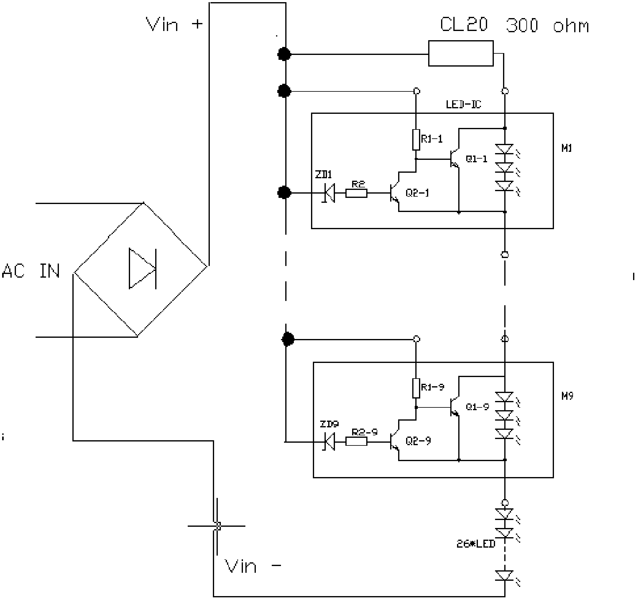
[0080] Such as figure 2 As shown: the connection relationship is as follows:
[0081] 1. The rectifier circuit is a bridge rectifier, the output positive pole is connected to the input terminal of the current limiting device and the first resistor in each LED module and the negative pole of the Zener diode of each threshold circuit are connected to form point C; each LED module is connected in series with the other 26 LEDs Continue to connect in series, the output negative pole Vin- of the rectifier circuit is connected to the negative pole of the last LED.
[0082] 2. CL20 is a current limiting device. Its input end is connected with the output positive pole of the rectification circuit, and its output end is connected with the input end of the LED in the first LED module.
[0083] 3. Each LED module is composed of an LED, a first switch Q1 and a first resistor R1, wherein the first resistor R1 is connected to...
PUM
 Abstract
Description
Claims
Application Information
 - R&D
- Intellectual Property
- Life Sciences
- Materials
- Tech Scout
- Unparalleled Data Quality
- Higher Quality Content
- 60% Fewer Hallucinations
Browse by: Latest US Patents, China's latest patents, Technical Efficacy Thesaurus, Application Domain, Technology Topic, Popular Technical Reports.
© 2025 PatSnap. All rights reserved.Legal|Privacy policy|Modern Slavery Act Transparency Statement|Sitemap|About US| Contact US: help@patsnap.com


