Gas insulated switchgear

A technology for gas-insulated switches and equipment, applied in electrical switches, high-voltage/high-current switches, electrical components, etc., can solve the problems of inappropriateness, simplified manufacturing process, and evaluation of the deterioration degree of permanent magnets, which takes a lot of effort and time. , to achieve the effect of low operating force and simple structure

Inactive Publication Date: 2014-12-24
HITACHI LTD
View PDF9 Cites 5 Cited by
  • Summary
  • Abstract
  • Description
  • Claims
  • Application Information

AI Technical Summary

Problems solved by technology

[0014] For example, in the case of an arc drive method using a permanent magnet structure, it is necessary to consider the design of the permanent magnet's deterioration over time due to the temperature change due to the current flowing during operation, and the evaluation of the degree of deterioration of the permanent magnet is costly. Extremely laborious and time-consuming, and thus not in principle suitable for efficiently rotating the driven arc in the case of interrupting the alternating current, since the direction of rotation of the arc is reversed every half cycle
[0015] In addition, in the case of the arc driving method using the structure of the arc driving coil, it is necessary to arrange the arc driving coil near the arc generating part, so that no current flows in the arc driving coil in a stable operating state. structure, the structure of this part is complicated and the outer diameter becomes large, which hinders the miniaturization of the equipment
[0016] Furthermore, in the case of an arc driving method using a structure of a spiral electrode, since many minute slits (spiral grooves) are formed over the electrode surface, insulation for preventing arc commutation is required between the slits. structure, and since the helical electrode is arranged at the front end of the arc contactor opposite to the fixed side and the movable side, it is necessary to set a transfer mechanism such as a spring in the arc contactor during the breaking action so that the helical electrode Physically separated last, the structure of this part is complicated and the simplification of the manufacturing process is not suitable

Method used


Image

  • Gas insulated switchgear
  • Gas insulated switchgear
  • Gas insulated switchgear

Examples


Embodiment 1

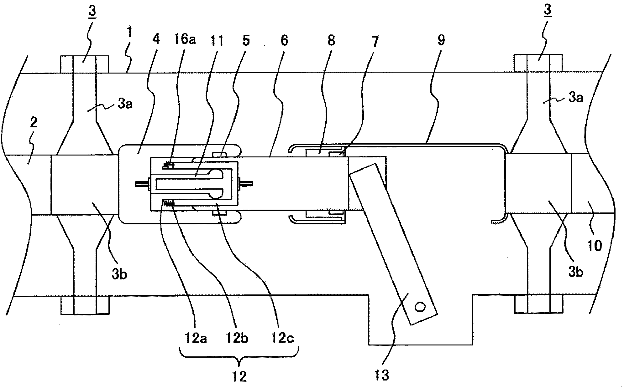
[0034] figure 1 It is a sectional view showing a closed state of the gas insulated switchgear according to the first embodiment of the present invention.

[0035] As shown in the figure, the gas insulated switchgear of this embodiment forms a gas compartment in the airtight container 1 through the support insulator 3, and seals SF in the gas compartment. 6 Negative gas such as gas, dry air, nitrogen, carbon dioxide, SF including negative gas 6 / N 2 Mixed gas, N excluding negative gas 2 / O 2 Mixed gas etc. are used as insulating gas.

[0036] The support insulator 3 is provided with an insulator 3a around it, and an embedded conductor 3b is arranged at the center, and the embedded conductor 3b supports and fixes the stator conductors 4 and The movable element conductor 9 and the opposing portions of these stator conductors 4 and the movable element conductor 9 are each formed in a curved shape, and the electric field relaxation shield effect is provided by being formed in ...

Embodiment 2

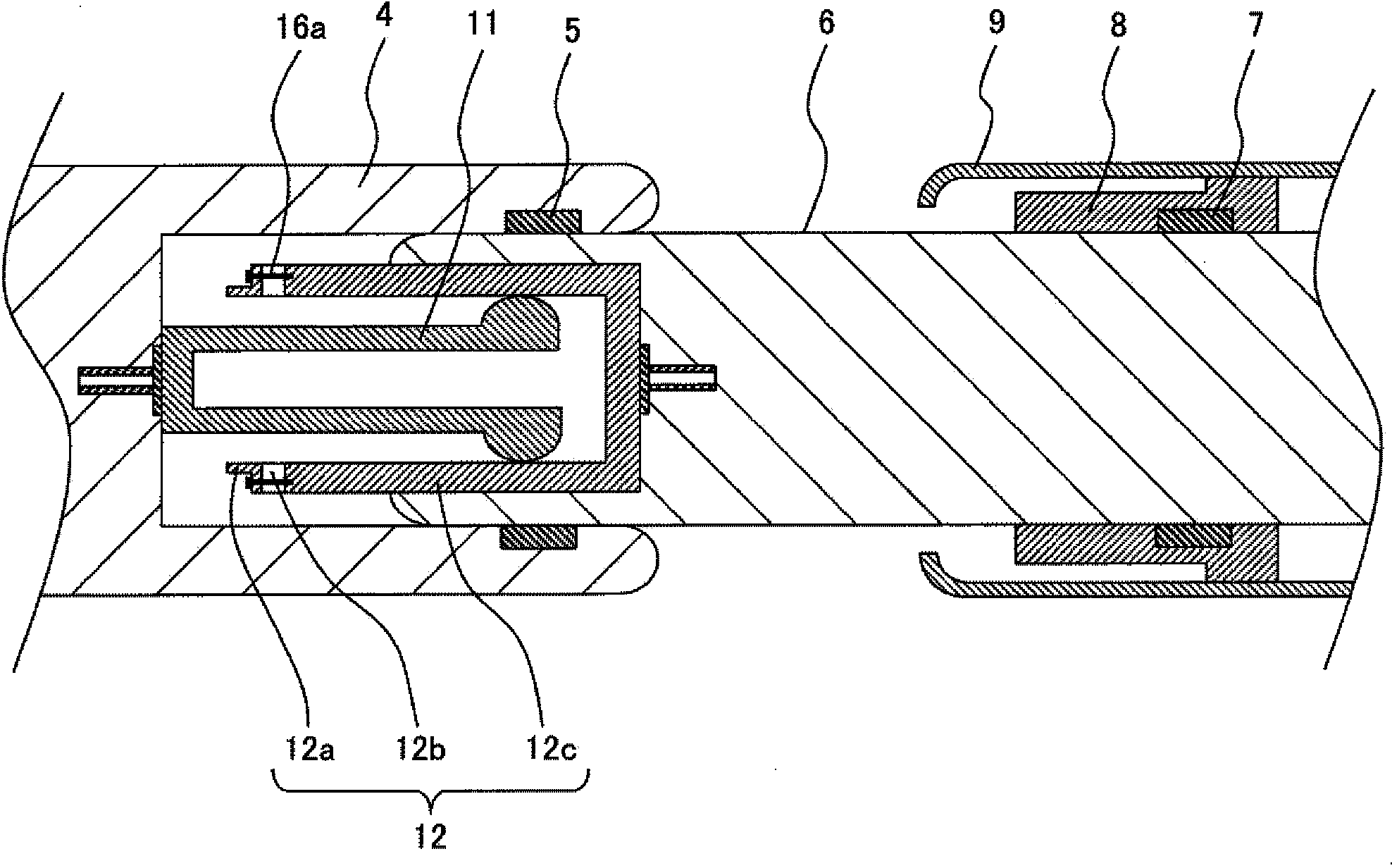
[0067] Figure 7 Shows the equivalent of another fixing method of the gas insulated switchgear according to Embodiment 2 of the present invention Figure 4 The enlarged cross-sectional view of the main part.

[0068]This embodiment is a modified example of the method of fixing the convex electrode 12a, the spacer 12b, and the cylindrical electrode 12c described in the first embodiment of the present invention, and differences from the first embodiment will be described here.

[0069] exist Figure 7 The present embodiment shown is characterized in that, in fixing the convex electrode 12a, the spacer 12b and the cylindrical electrode 12c, a fixing member 16b made of metal such as SUS is used to ensure the stability described in the first embodiment. The fixing strength of the insulating fixing member 16a or more.

[0070] That is, in this embodiment, if Figure 7 As shown, a metal fixing member 16b is used to fix the convex electrode 12a, the spacer 12b and the cylindrical ...

Embodiment 3

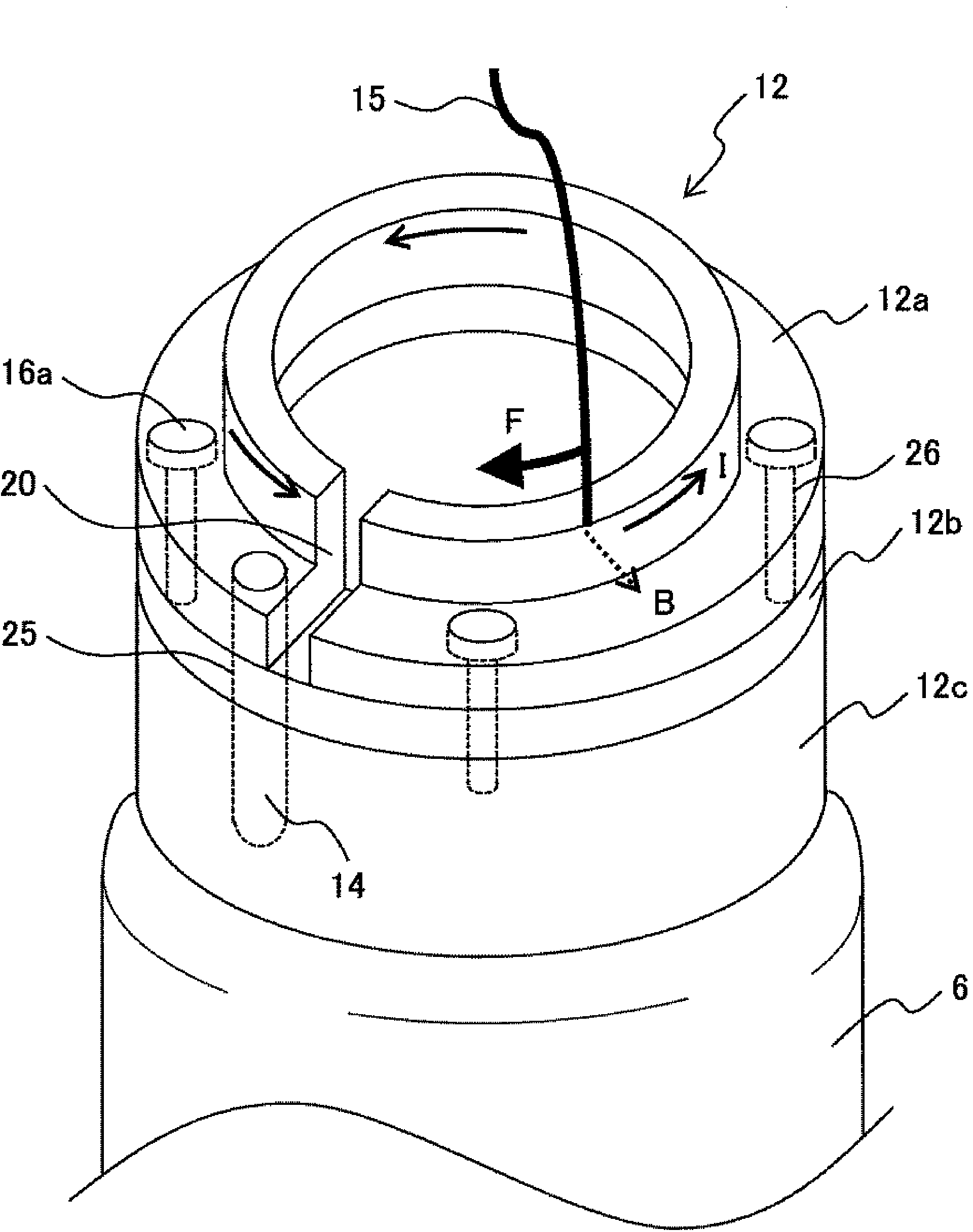
[0075] Figure 8 It is a perspective view viewed from the direction of the opposite front end of the movable arc contactor 12 of the gas insulated switchgear according to Embodiment 3 of the present invention.

[0076] This embodiment is a modified example using the method of fixing the convex electrode 12a, the spacer 12b, and the cylindrical electrode 12c described in Embodiments 1 and 2 of the present invention. Here, differences from Embodiment 2 will be described. .

[0077] Such as Figure 8 As shown, in this embodiment, it is characterized in that the width w generated by the difference in the distance between the outer diameter of the large-diameter portion and the outer diameter of the small-diameter portion of the convex electrode 12a 1 A ring-shaped (cylindrical) insulating fixing spacer 19 that is a third spacer is arranged in the middle, and the convex electrode 12a, the spacer 12b and the cylindrical electrode 12c are fixed by the fixing spacer 19 .

[0078] u...


PUM


Abstract

Compact lightweight gas insulated switchgear which assures sufficient electrode fixing strength equivalent to the fixing strength given by brazing and is structurally simple and enables efficient arc rotation with low operating energy. In the switchgear, a movable arcing contact is located on a movable element, opposite to a fixed arcing contact and electrically connected to, or disconnected from, the fixed arcing contact as the movable element moves. The movable arcing contact includes, in order from its tip opposite to the fixed arcing contact, a first electrode as a convex hollow coaxial cylindrical electrode, hollow coaxial cylindrical first spacer, and second electrode as a hollow coaxial cylindrical electrode and has electric conduction means to connect the first and second electrodes electrically through the first spacer. The first and second electrodes are fixed through the first spacer by a fixing member having higher resistivity than the first and second electrodes.

Description

technical field [0001] The present invention relates to gas insulated switchgear (Gas Insulated Switchgear), in particular to a gas insulated switchgear suitable for having arc contactors that are in electrical contact with each other when closed, and arc-ignited when opened. Background technique [0002] In general, in gas insulated switchgear, arc contactors are arranged to prevent damage to the main contactor or shield for energization due to arc discharge generated at the time of opening, and the fixed side is arranged with a predetermined opposing distance. conductors and conductors on the movable side. Furthermore, there is known a structure in which an arc contactor is arranged on a fixed-side conductor, an arc contactor is arranged on a movable-side conductor, and an arc contactor is respectively arranged on a movable element, and furthermore, an arc contactor is arranged at the front end of the fixed-side or movable-side arc contactor. The elastic contact part is a...

Claims


Application Information

Patent Timeline
Patent Type & Authority Applications(China)
IPC IPC(8): H01H33/70
CPCH01H33/12H01H33/18H01H33/64
Inventor 森山智广额贺淳六户敏昭川又雅史
Owner HITACHI LTD
Why Eureka
Try Eureka