
Camera support with telescopic clamping portions

A technology of a clamping part and a camera mount, applied in the field of camera mounts, can solve the problem of limited support effect, etc., and achieve the effects of good force application, convenient clamping and flexible adjustment

Active Publication Date: 2014-12-24
HUAQIANG FANGTE WUHU CULTURE TECH CO LTD
View PDF6 Cites 1 Cited by
  • Summary
  • Abstract
  • Description
  • Claims
  • Application Information

AI Technical Summary

Problems solved by technology

[0006] However, in specific use, since the connecting rods are connected by screws, the frictional force of the connecting rods on the support body is provided by the pressure of the connecting rods on the support body, and the pressure is provided by the tightening force of the screws. After decomposing layer by layer, even if the screw has a strong fastening force, it becomes very small after being decomposed into the friction force of the connecting rod on the support body, especially when the support body is an object with a small surface friction coefficient such as a utility pole. Moreover, due to the large number of connecting rods, it is difficult to ensure that each bolt has a strong fastening force, so the supporting effect is limited

Method used


Image

  • Camera support with telescopic clamping portions
  • Camera support with telescopic clamping portions
  • Camera support with telescopic clamping portions

Examples


Embodiment Construction

[0024] In order to make the technical means, creative features, goals and effects achieved by the present invention easy to understand, the present invention will be further described below in conjunction with specific illustrations.

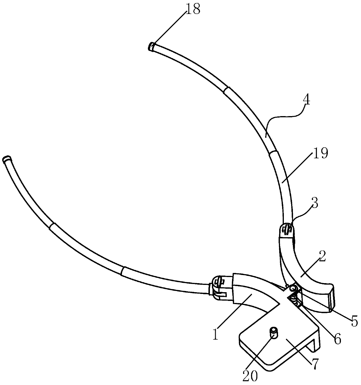
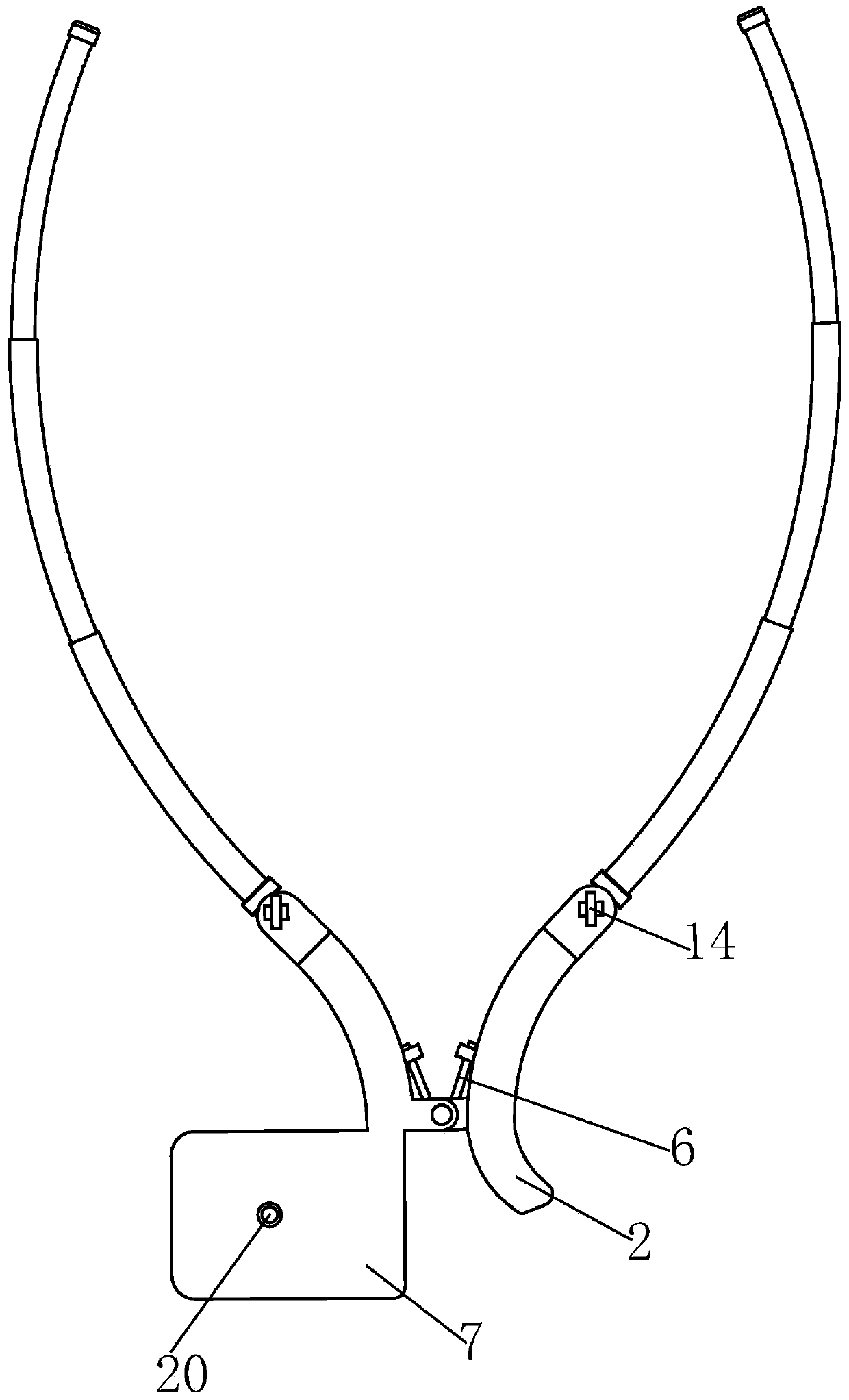
[0025] Such as Figure 1 to Figure 5 As shown, a camera frame with a retractable clamping part includes a No. 1 base body 1 and a No. 2 base body 2, and the rear ends of the No. 1 base body 1 and No. 2 base body 2 are provided with an orientation part 3 and a clamping part. Part 4, a central axis 5 is provided between the No. 1 base body 1 and the No. 2 base body 2, and the No. 1 base body 1 and the No. 2 base body 2 are connected to the central shaft 5 in a hinged manner. The central shaft 5 is covered with a torsion A spring 6, the torsion spring 6 presses the rear parts of the No. 1 base body 1 and the No. 2 base body 2 together, and the upper part of the No. 1 base body 1 is provided with a stage 7 for placing an imaging tool.

[0026] A gr...


PUM


Abstract

The invention relates to a camera support with telescopic clamping portions. The camera support with the telescopic clamping portions comprises a first base body and a second base body. The rear end of the first base body and the rear end of the second base body are respectively provided with a directional portion and one clamping portion. A middle shaft is arranged between the first base body and the second base body. The first base body and the second base body are connected to the middle shaft in a hinged mode. A torsion spring is arranged on the middle shaft in a sleeved mode. The rear portion of the first base body and the rear portion of the second base body are pulled close through the torsion spring. A carrying platform is arranged on the upper portion of the first base body. A groove is formed in the middle of each directional portion. A rotating disk is arranged at one end of each clamping portion. The rotating disk is connected into the groove in a hinged mode. A lower toothed disk is arranged on the upper end face of the rotating disk. The upper toothed disk and the lower toothed disk are matched with each other. The upper toothed disk has the locating function on the lower toothed disk, the included angle between the clamping portion and the carrying platform holding a shooting tool can be flexibly adjusted, the flexibility of shooting is improved, and the shooting angle is convenient to adjust; due to the fact that the telescopic structure is adopted by the clamping portion, clamping is carried out conveniently through the clamping portion, and the application range of the camera support is widened.

Description

technical field [0001] The invention relates to the technical field of supporting devices for photographing and imaging equipment, in particular to a camera frame with a retractable clamping part. Background technique [0002] Camera is also called computer camera, computer eye, etc. As a video input device, it has been widely used in video conferencing, telemedicine and real-time monitoring in the past. In recent years, with the development of Internet technology, the continuous improvement of network speed, coupled with the maturity of photosensitive imaging device technology and its extensive use in the manufacture of cameras, this has reduced its price to a level that ordinary people can afford. Mobile phones are the field with the most camera applications. As early as 2007, when Nokia released the N95, people encountered it. At that time, the N95 was equipped with a 500W Carl Zeiss certified camera, which made the N95 the focus of attention at that time. Years later, N...

Claims


Application Information

Patent Timeline
Patent Type & Authority Applications(China)
IPC IPC(8): F16M11/06F16M11/16G03B17/56H04M1/12
Inventor 陈祖尧易伟林
Owner HUAQIANG FANGTE WUHU CULTURE TECH CO LTD
Learn More