
An eccentric locking assembly and a method for assembling a hollow profile

A hollow profile and eccentric locking technology, which is applied in the direction of connecting components, mechanical equipment, etc., can solve the problems of hollow profile end face joints and sharp corners that are difficult to eliminate, and achieve the effect of improving the aesthetics of the closing, single variety, and simple component structure

Active Publication Date: 2017-02-22
乐陵市鑫通彩钢板有限公司
View PDF4 Cites 0 Cited by
  • Summary
  • Abstract
  • Description
  • Claims
  • Application Information

AI Technical Summary

Problems solved by technology

[0002] At present, hollow profiles have been widely used in the fields of building doors and windows processing, wood furniture manufacturing, or interior decoration. The most common application method is to cut the ends of hollow profiles into 45-degree or 90-degree angles for splicing. frame, and install glass, wood boards or pictorial panels in the middle of the frame, and frame-type products such as doors and windows, picture frames, screens, TV background walls or furniture components that constitute frame structures, in the process of splicing and framing, most The ends of the hollow profiles are connected and fixed by using hardware corner codes and screws, and a few use adhesives or high-frequency welding technology to bond and fix the ends of the hollow profiles. The biggest defect of these two methods is that it is difficult to eliminate the hollow profiles. The flat seams and sharp corners of the end face affect the aesthetics and safety of the product. Therefore, an installation connection component and its assembly with a relatively simple structure, relatively rounded corners, beautiful seam closure, and easy installation and operation have been developed. The frame method has become a major topic urgently awaiting innovation and breakthrough in the application and construction of hollow profiles

Method used


Image

  • An eccentric locking assembly and a method for assembling a hollow profile
  • An eccentric locking assembly and a method for assembling a hollow profile
  • An eccentric locking assembly and a method for assembling a hollow profile

Examples


Embodiment Construction

[0017] Below by example in conjunction with accompanying drawing, the present invention will be further elaborated:

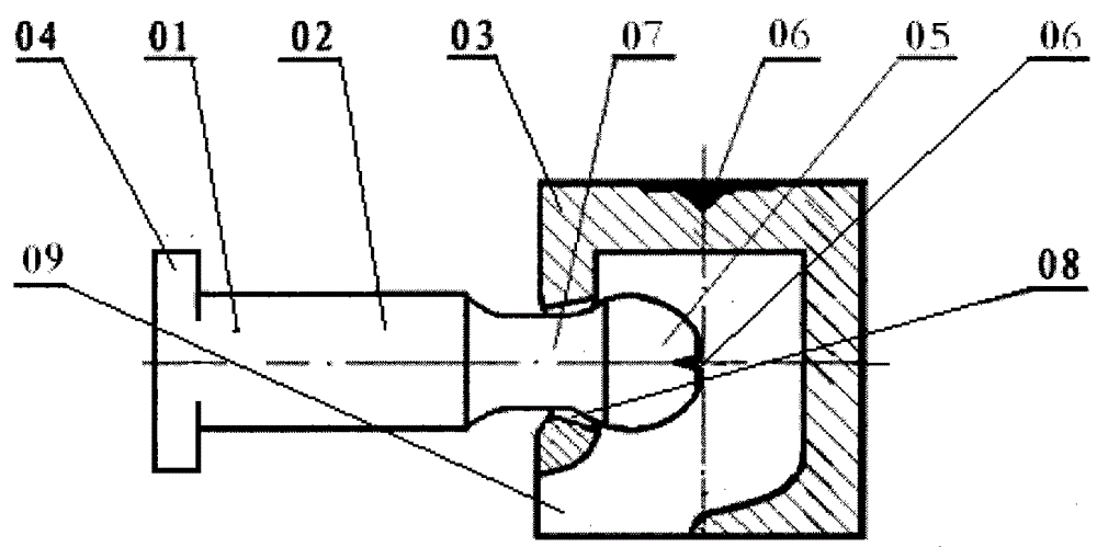
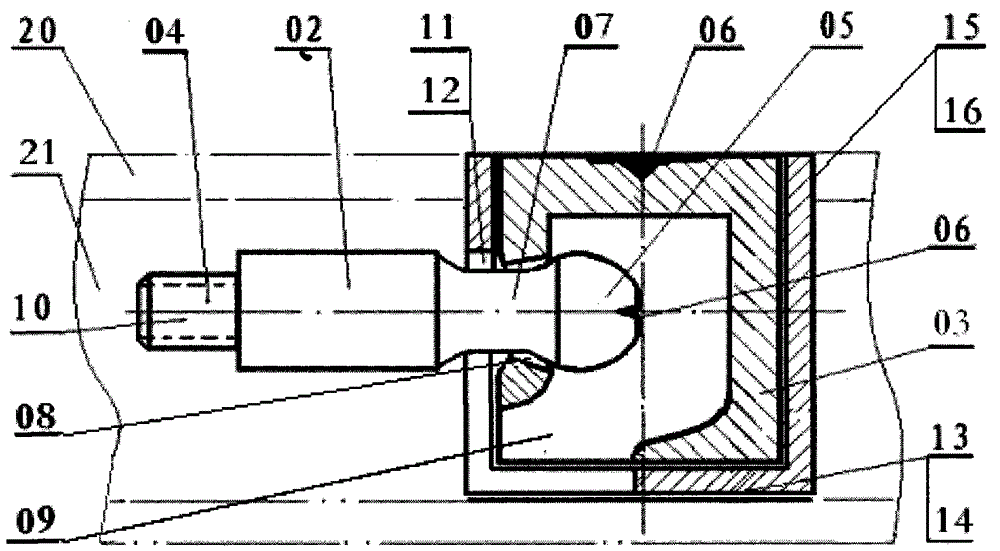
[0018] figure 1 It is a structural schematic diagram of an embodiment of the eccentric locking assembly of the present invention. (01) in the figure is an eccentric locking assembly, which is elongated in appearance and is composed of a columnar connecting rod (02) and a cylindrical eccentric member (03). One end of the connecting rod (02) is made of Or "T"-shaped or "Γ"-shaped or dovetail-shaped or screw-shaped buckle head (04), the other end is shaped on a spherical head (05) with a spherical crown, and the top of the spherical head (05) is shaped on a concave "ten". "Word screwdriver groove (06), is shaped on concave annular groove (07) at the connecting position of spherical head (05) and connecting rod (02). The upper end surface of the eccentric member (03) is formed with a concave "ten" screwdriver groove (06), and the lower end surface is formed with ...


PUM


Abstract

The invention discloses an eccentric locking component and a hollow profile framing method thereof. The hollow profile framing method is mainly characterized in that hollow profiles, corner connecting pieces and an embedded plate are framed by a plurality of groups of eccentric locking components so as to form a polygonal frame plate type product, or frame plate type products are assembled by the eccentric locking components and the hollow profiles so as to form a stereoscopic frame-type product. The eccentric locking component is formed by combining a bar-column-shaped connection rod with a cylindrical eccentric part. Four peripheral edges of the embedded plate are embedded into mounting clamp grooves of the hollow profiles, two arms of the corner connecting pieces are inserted into hollows of the end tips of the hollow profiles respectively, the eccentric parts are implanted into inner cavities of mounting supports, and mounting holes are pushed to corner directions under the action of eccentric displacement quantity by rotating the eccentric parts, so that the end tips of the hollow profiles and the stepped side faces of projections are adhered.

Description

technical field [0001] The invention relates to an eccentric locking assembly in the hardware manufacturing industry, and particularly relates to the specific structure of the assembly and its method for framing the hollow profile. Background technique [0002] At present, hollow profiles have been widely used in the fields of building doors and windows processing, wood furniture manufacturing, or interior decoration. The most common application method is to cut the ends of hollow profiles into 45-degree or 90-degree angles for splicing. frame, and install glass, wood boards or pictorial panels in the middle of the frame, and frame-type products such as doors and windows, picture frames, screens, TV background walls or furniture components that constitute frame structures, in the process of splicing and framing, most The ends of the hollow profiles are connected and fixed by using hardware corner codes and screws, and a few use adhesives or high-frequency welding technology ...

Claims


Application Information

Patent Timeline
Patent Type & Authority Patents(China)
IPC IPC(8): F16B17/00
Inventor 姚本海
Owner 乐陵市鑫通彩钢板有限公司
Learn More