System and method for a movable exhaust aftertreatment device in an internal combustion engine

A technology of exhaust post-treatment and internal combustion engine, which is applied in the direction of electronic control of exhaust treatment device, internal combustion piston engine, exhaust device, etc., and can solve the problem of not providing flow control, etc.

Active Publication Date: 2018-07-03
FORD GLOBAL TECH LLC
View PDF12 Cites 0 Cited by
  • Summary
  • Abstract
  • Description
  • Claims
  • Application Information

AI Technical Summary

Problems solved by technology

Another potential problem with the above approach of Gudorf et al., which the inventors are aware of is that it does not provide flow control

Method used


Image

  • System and method for a movable exhaust aftertreatment device in an internal combustion engine
  • System and method for a movable exhaust aftertreatment device in an internal combustion engine
  • System and method for a movable exhaust aftertreatment device in an internal combustion engine

Examples


Embodiment Construction

[0030] Hereinafter, the present invention will be explained in more detail based on a number of exemplary embodiments and with reference to the accompanying drawings.

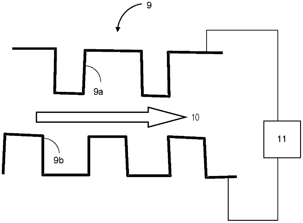
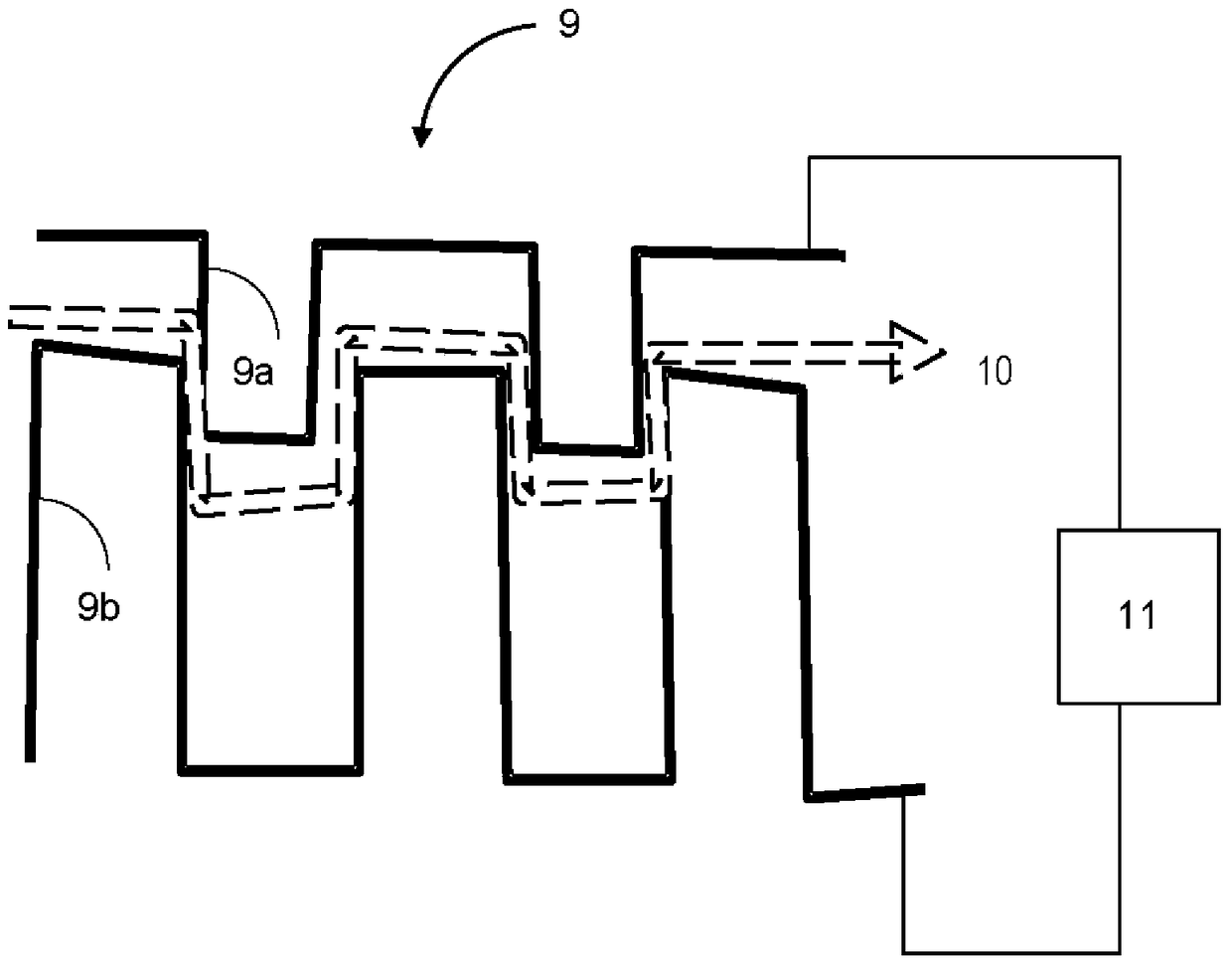
[0031] figure 1 is a schematic illustration for explaining the configuration of the exhaust aftertreatment device 3 including the filter passage 9 in the exhaust system 1 of the vehicle.

[0032] exist figure 1 In this case, an internal combustion engine 2 with a turbocharger 22 , for example a diesel engine, introduces fresh air from an air filter 4 , which is precompressed by a compressor 22 a of the turbocharger 22 . In the exhaust line 5 downstream of the turbine 22b of the turbocharger 22, the exhaust gas of the internal combustion engine 2 flows successively through the oxidation catalytic converter and / or the NOx storage catalytic converter 6, the diesel particulate filter 7 and the rear muffler 8.

[0033] Control system 14 may include a plurality of sensors 16 that send signals to controller 12 . A...


PUM


Abstract

The present invention relates to an exhaust gas aftertreatment device and a method for exhaust gas aftertreatment. According to one aspect of the invention, the exhaust gas aftertreatment device has a filter passage in an exhaust manifold of an internal combustion engine, the filter passage having a passage path for the exhaust gas flow, the passage path after the exhaust gas aftertreatment The operation of the device is variably adjusted over time.

Description

[0001] Cross References to Related Applications [0002] This application claims priority from German Patent Application No. 102013211293.9 filed on June 17, 2013, which is hereby incorporated by reference in its entirety for all purposes. technical field [0003] The invention relates to an exhaust gas aftertreatment device and a method for exhaust gas aftertreatment. Background technique [0004] In motor vehicles with diesel engines, exhaust gas aftertreatment devices equipped with NOx storage catalytic converters and operated with a rich air-fuel mixture are implemented in certain operating phases. In this case, a relatively low target value (for example 0.96) is set for the lambda value which is taken into account for releasing and converting nitrogen oxides (NOx) stored in the NOx storage catalytic converter and It is also used to release sulfur at relatively low catalytic converter temperatures (typically 600°C-700°C). [0005] During low-load operation, the stabili...

Claims


Application Information

Patent Timeline
Patent Type & Authority Patents(China)
IPC IPC(8): F01N3/022F01N9/00
CPCF01N3/0842F01N3/106F01N9/00F02B37/22F01N3/022B01D2275/302F01N2260/14F01N2560/025F01N2900/08Y02T10/12Y02T10/40F01N13/10
Inventor Y·M·S·雅克布
Owner FORD GLOBAL TECH LLC
Why Eureka
Try Eureka