Eureka AIR delivers breakthrough ideas for toughest innovation challenges, trusted by R&D personnel around the world.

Two-stage drive complex high-frequency vibration sieve

A technology of compound vibration and high-frequency sieve, which is applied in the direction of mobile filter element filter, filter separation, separation method, etc., to achieve the effect of reducing the quality of vibration, convenient adjustment and easy installation

Inactive Publication Date: 2014-12-24
TANGSHAN BRANCH COAL SCI ACAD
View PDF6 Cites 3 Cited by
  • Summary
  • Abstract
  • Description
  • Claims
  • Application Information

AI Technical Summary

Problems solved by technology

[0003] The technical problem to be solved by the present invention is to provide a dual-stage drive composite vibrating high-frequency screen. This composite vibrating high-frequency screen can overcome the shortcomings of existing high-frequency screens, and has the advantages of good dehydration effect, low energy consumption, high reliability, The advantages of being large-scale can solve technical problems that have not been solved for a long time, which not only promotes the development of high-frequency vibrating screens, but also brings greater economic benefits to enterprises

Method used

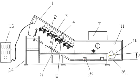
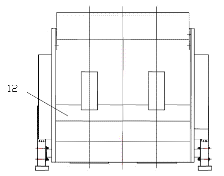

Image

  • Two-stage drive complex high-frequency vibration sieve
  • Two-stage drive complex high-frequency vibration sieve

Examples


Embodiment Construction

[0020] The high-frequency vibrating screen of the present invention is divided into two sections: the upper section of the high-frequency screen and the lower section 9 of the high-frequency screen. The vibrating devices installed in the upper section of the high-frequency screen 1 and the lower section 9 of the high-frequency screen are independently driven, and the two sections are independent units. They are connected together by the elastic device 8 to interact and influence each other to achieve a novel compound vibration effect.

[0021] The figure shows that the upper section 1 of the high-frequency screen is installed at a large positive angle with the feed end higher than the discharge end, and the lower section 9 of the high-frequency screen adopts a small positive angle or a small positive angle between the feed end and the discharge end or the feed end is lower than the discharge end. Negative angle installation. The installation angle α of the upper screen or sieve p...


PUM

PropertyMeasurementUnit
lengthaaaaaaaaaa

Abstract

A two-stage drive complex high-frequency vibration sieve belongs to the technical field of high-frequency vibration sieves and is used for dewatering operations for fine materials such as coal slime, tailings and sand and gravel. The technical scheme is that the sieve is of a structure of dual bodies of an upper high-frequency sieve section and a lower high-frequency sieve section, wherein the upper high-frequency sieve section is mounted at a large positive angle with the feed end higher than the discharge end, the lower high-frequency sieve section is mounted at a small positive angle with the feed end almost parallel to the discharge end or at a negative angle with the feed end lower than the discharge end, the lower high-frequency sieve section is connected to the rear portion of the discharge end of the upper high-frequency sieve section through an elastic member, the upper high-frequency sieve section and the lower high-frequency sieve section are respectively mounted with an independent vibration device, and the upper high-frequency sieve section and the lower high-frequency sieve section are up to 4500mm in the width of the sieve surface and up to 6000mm in the total length of the sieve surface. The two-stage drive complex high-frequency vibration sieve has the advantages of being reliable in operation, large scale achievable, good in dewatering effect and low in energy consumption and the like, solves the long-term unsolved technical problems of high-frequency vibration sieves, facilitates the development of the high-frequency vibration sieves, and has significant economic benefits.

Description

Technical field [0001] The invention relates to a high-frequency vibrating dewatering screen used for dewatering fine-grained materials such as coal slime, tailings, sand and gravel, and belongs to the technical field of high-frequency vibrating screen equipment. Background technique [0002] At present, high-frequency vibrating screens have been widely used in the dehydration process of coarse slime dehydration, tailings dehydration, sand and gravel dehydration and other fine materials. The high-frequency vibrating screen has three types of structures: electromagnetic vibrating high-frequency screen, mechanical vibrating high-frequency screen and electromagnetic and mechanical composite vibrating high-frequency screen, each of which has advantages and disadvantages. The electromagnetic vibrating high-frequency screen has good reliability and can be large-scaled, but the moisture content on the screen is too high, and the dehydration effect is not good; the mechanical vibrating h...

Claims


Application Information

Patent Timeline
Patent Type & Authority Applications(China)
IPC IPC(8): B01D33/03B01D33/41
Inventor 卢志明梁浩梁金钢王忠文王凤芝贾云峰张磊段海鹏徐旭东陈捷频安连红
Owner TANGSHAN BRANCH COAL SCI ACAD
Why Eureka
Eureka Blog
Learn More