Polyphase reluctance motor
A reluctance motor and excitation technology, applied in electrical components, electromechanical devices, magnetic circuit static parts, etc., can solve the problem of low torque density of the motor, widen the range of constant power speed regulation, simple and sturdy structure, and high efficiency Effect
- Summary
- Abstract
- Description
- Claims
- Application Information
AI Technical Summary
Problems solved by technology
Method used
Image


Examples
specific Embodiment approach 1
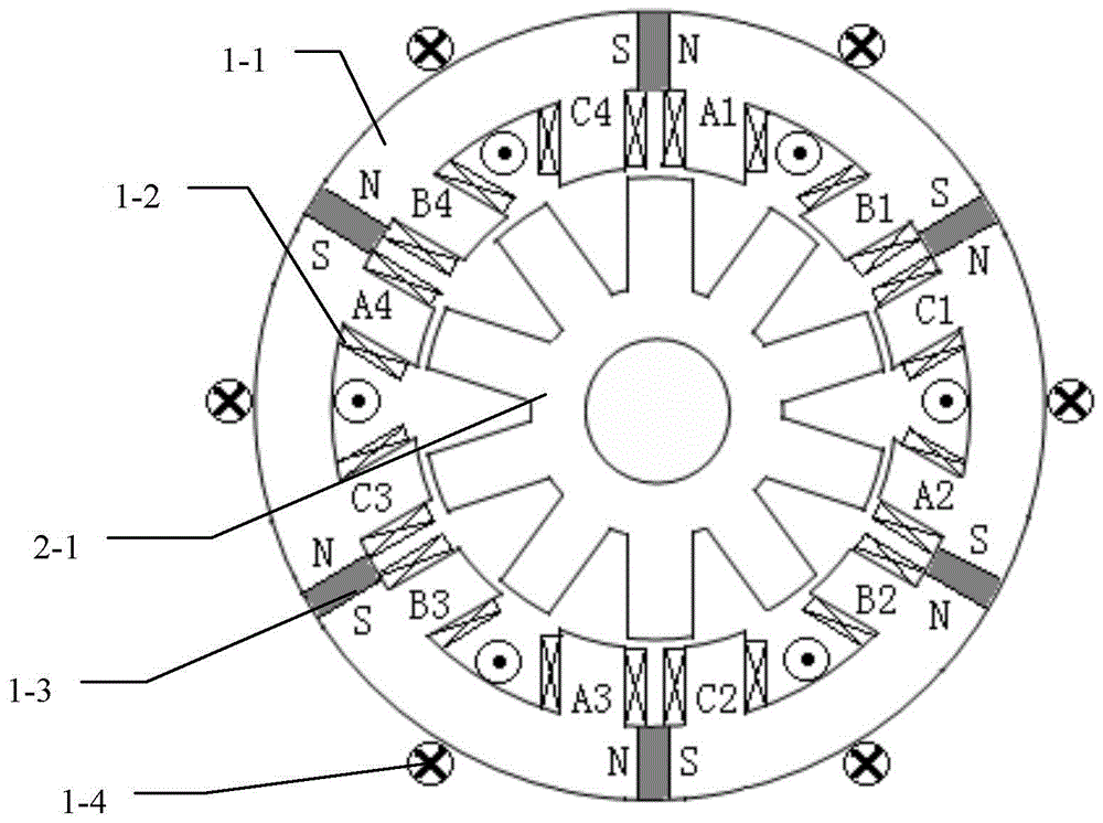
[0046] Specific implementation mode one: the following combination Figure 1 to Figure 9 Describe this embodiment, the polyphase reluctance motor described in this embodiment includes a stator and a rotor, an air gap is formed between the stator and the rotor, the stator includes an armature core 1-1, an armature winding 1-2 and an excitation unit,
[0047] The armature core 1-1 is cylindrical, and the air gap side surface of the armature core 1-1 has a plurality of axial slots, forming a structure in which the stator poles and stator slots are arranged at intervals along the circumferential direction; An armature coil is wound, and the armature coils belonging to the same phase are connected in series along the circumferential direction of the armature core 1-1 to form a phase armature winding, and the multi-phase winding composed of all phase armature windings is the armature winding 1-2;
[0048] The excitation unit is set on the armature core 1-1 yoke or the stator pole; ...
specific Embodiment approach 2
[0050] Specific implementation mode two: the following combination figure 1 and figure 2 Illustrate this embodiment, this embodiment will further describe embodiment one, the excitation unit is made up of main permanent magnet excitation unit 1-3 and electric excitation unit 1-4,
[0051] The main permanent magnet excitation unit 1-3 includes a plurality of flat main permanent magnets, the electric excitation unit 1-4 is composed of a plurality of excitation coils connected in series end to end, and the flat main permanent magnet is embedded in the corresponding armature core 1 at the bottom of the stator slot In the middle of the -1 yoke, each excitation coil is wound in the middle of the armature core 1-1 corresponding to the bottom of a stator slot, and all the excitation coils are wound in the same direction; the flat main permanent magnet and the excitation coil are along the armature core 1 -1 yokes arranged alternately;
[0052] The flat main permanent magnets are m...
specific Embodiment approach 3
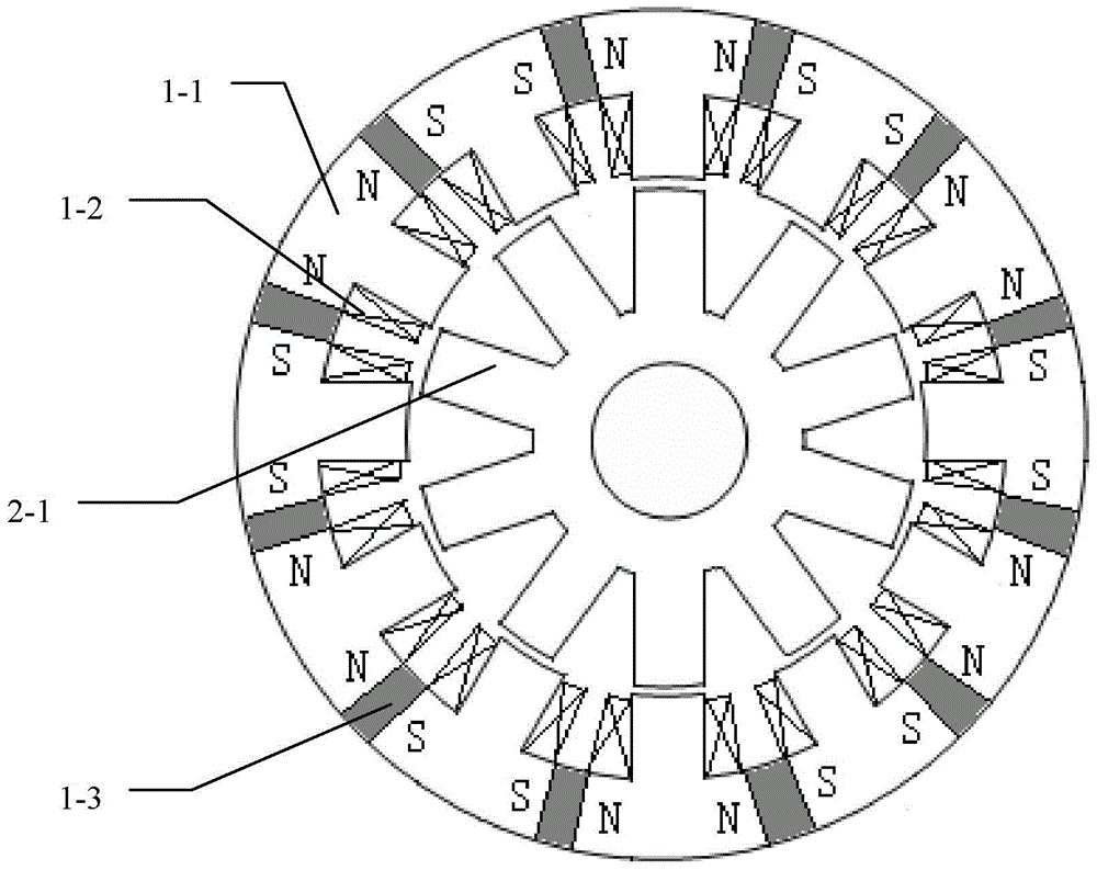
[0059] Specific implementation mode three: the following combination image 3 Describe this embodiment, this embodiment will further explain Embodiment 1, the excitation unit is the main permanent magnet excitation unit 1-3, the main permanent magnet excitation unit 1-3 includes a plurality of flat main permanent magnets, each stator slot bottom A plate-shaped main permanent magnet is embedded in the middle of the yoke of the corresponding armature core 1-1;
[0060] The flat-shaped main permanent magnet is magnetized tangentially along the circumference, and the magnetization direction of adjacent flat-shaped main permanent magnets is opposite;
[0061] The flat main permanent magnet is a rare earth permanent magnet.
[0062] In this embodiment, the flat main permanent magnet is made of a rare earth permanent magnet with high remanence and high coercive force.
[0063] image 3 Among them, there are 12 flat main permanent magnets.
PUM
 Abstract
Description
Claims
Application Information
 - R&D
- Intellectual Property
- Life Sciences
- Materials
- Tech Scout
- Unparalleled Data Quality
- Higher Quality Content
- 60% Fewer Hallucinations
Browse by: Latest US Patents, China's latest patents, Technical Efficacy Thesaurus, Application Domain, Technology Topic, Popular Technical Reports.
© 2025 PatSnap. All rights reserved.Legal|Privacy policy|Modern Slavery Act Transparency Statement|Sitemap|About US| Contact US: help@patsnap.com