
Base coordinate calibration method of two-robot collaboration system

A dual-robot, collaborative system technology, applied in the direction of instruments, measuring devices, etc., can solve the problems of expensive precision instruments, poor operability, and high cost

Active Publication Date: 2014-12-17
SOUTHEAST UNIV
View PDF6 Cites 23 Cited by
  • Summary
  • Abstract
  • Description
  • Claims
  • Application Information

AI Technical Summary

Problems solved by technology

The installation method is not flexible enough. Once the robot moves, the original calibration results will no longer be applicable. It is necessary to re-calibrate the new installation position with precision instruments, which is time-consuming and labor-intensive, and delays the production schedule.
However, the price of precision instruments is expensive and the measurement speed is slow, and it is becoming more and more unsuitable for the current high-efficiency production work.
[0004] At present, there are not many researches on the calibration of dual-robots at home and abroad, most of which are measured by precision instruments, and then some methods are used to improve the measurement results, which have some insurmountable difficulties: (1) Poor flexibility, time-consuming and labor-intensive measurement work, Delay the production progress; (2) The steps are complicated and the operability is poor, and relevant professionals are required to be competent; (3) The measuring instruments require high precision and are generally expensive, which increases the cost

Method used


Image

  • Base coordinate calibration method of two-robot collaboration system
  • Base coordinate calibration method of two-robot collaboration system
  • Base coordinate calibration method of two-robot collaboration system

Examples


Embodiment Construction

[0051] The present invention will be further described below in conjunction with the accompanying drawings and specific embodiments.

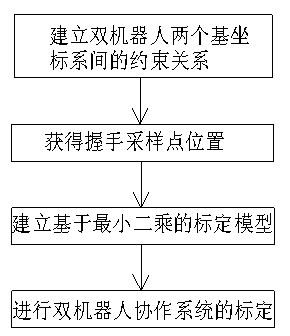
[0052] figure 1 It is a schematic flow chart of the collaborative robot calibration method proposed by the present invention. As shown in the figure, the collaborative robot calibration method according to the present invention includes the following steps:

[0053] Step 1: Establish the constraint relationship between the two base coordinate systems of the dual robot: According to the coordinate transformation relationship between the dual robots in the collaborative system, establish the constraint relationship between the two base coordinate systems of the dual robot.

[0054] According to the respective base frames of the two robots in the collaborative system, the base frame of one robot is used as the world coordinate system, and the transformation relationship of the base frame of the other robot with respect to the world coordinate sys...


PUM


Abstract

The invention discloses a base coordinate calibration method of a two-robot collaboration system. The base coordinate calibration method comprises the steps of firstly, establishing geometric constraint between the base coordinate systems of two robots according to a coordination transformation relation between the two robots in the collaboration system, secondly, performing a plurality of handshake action experiments of the two robots by use of a calibration finger mounted on the tail end of a tool hand to obtain the coordinates of the handshake sampling points of the two robots under the own coordinate systems, respectively, thirdly, building a calibration model according to the handshake sampling points and the robot base coordinate constraint, and finally, solving by use of a singular value decomposition algorithm to obtain a rotation matrix and a translation vector between the base coordinates of the two robots, and consequently, completing the calibration of the two-robot collaboration system. The base coordinate calibration method of the two-robot collaboration system does not rely on other external special measuring devices, and is simple and easy to implement; besides, the base coordinate calibration method is high in calibration accuracy by use of a numerical solution method, and also has excellent error fault-tolerant capability, and therefore, the processing level and the production quality of the two-robot collaboration system can be well improved.

Description

technical field [0001] The invention relates to the technical field of advanced manufacturing of industrial robots such as welding, cutting, spraying, and handling, and in particular to a method for calibrating base coordinates of a dual-robot collaborative system. Background technique [0002] As automation equipment, industrial robots are not affected by the working environment, work stably and reliably, and because of their programmability, work efficiency is greatly improved and production costs are reduced. At present, in dealing with tasks such as fixture-free system welding, the ability of a single robot is more and more insufficient, so dual-robot and even multi-robot systems are gradually being applied to various fields. Through coordination and cooperation, multiple robots can complete complex tasks that are difficult for a single robot, improve production efficiency, and solve more practical application problems. [0003] In traditional dual-robot collaborative s...

Claims


Application Information

Patent Timeline
IPC IPC(8): G01B21/04
Inventor 周波戴先中孟正大张曦
Owner SOUTHEAST UNIV
Learn More