


Quick Research
Generate reliable direction feasibility study reports for your R&D in just a few steps.

Technical Q&A
Discover and master advanced knowledge NOW. Basics, ideas, possibilities, all at once.

Find Solutions
As an expert in R&D theories, this can generate solutions to your technical problems instantly.

Evaluate Feasibility
Analyze your overall solution with one click, know your potential R&D risks in advance.

Monitor Landscape
Get weekly tech updates, stay abreast of the latest tech innovations and key insights.
Pneumatic clamping machine for lifting and self-weight turning of steel pipe for heating
A technology of pneumatic clamps and steel pipes, applied in the direction of load hanging components, transportation and packaging, etc., can solve the problems that have not yet been achieved, and achieve the effect of convenient operation and simple structure
- Summary
- Abstract
- Description
- Claims
- Application Information
AI Technical Summary
Problems solved by technology
Method used
Image

Examples
specific Embodiment approach 1
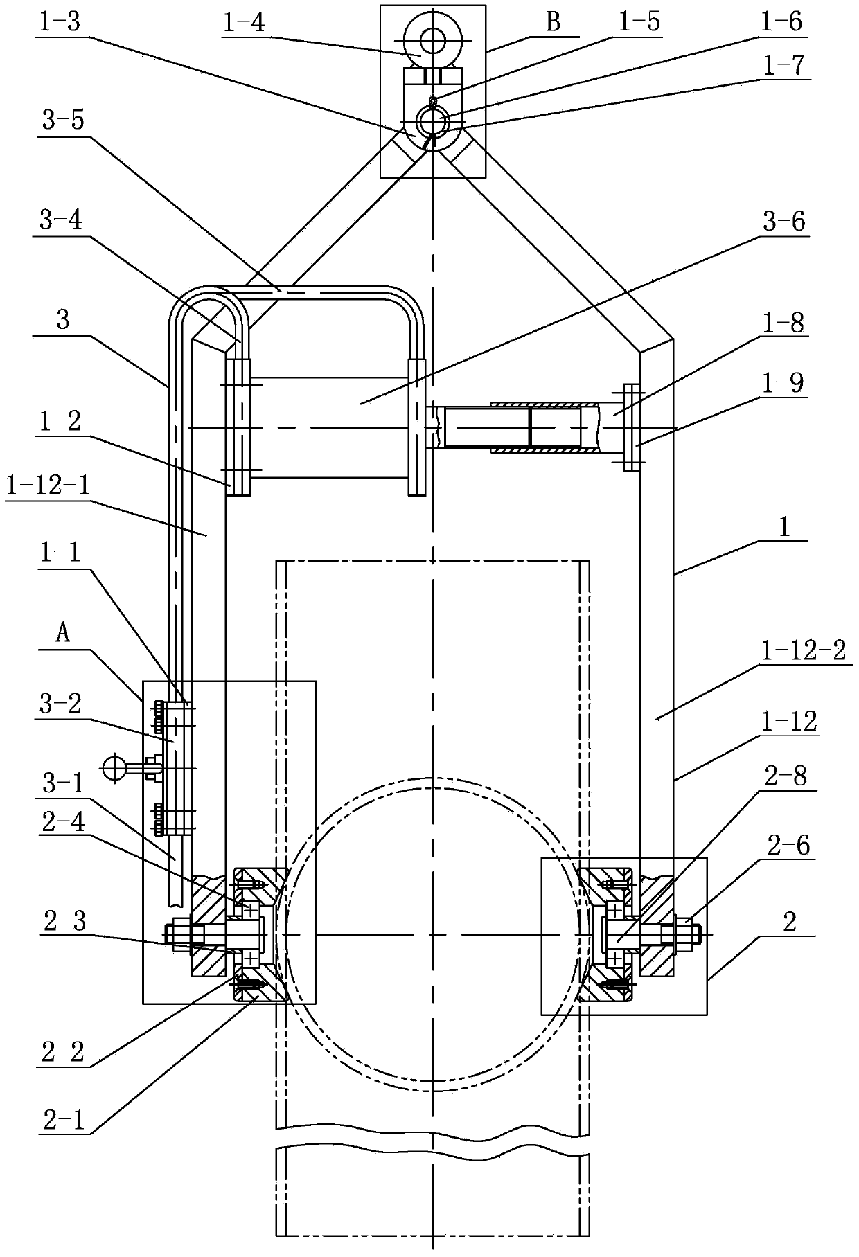
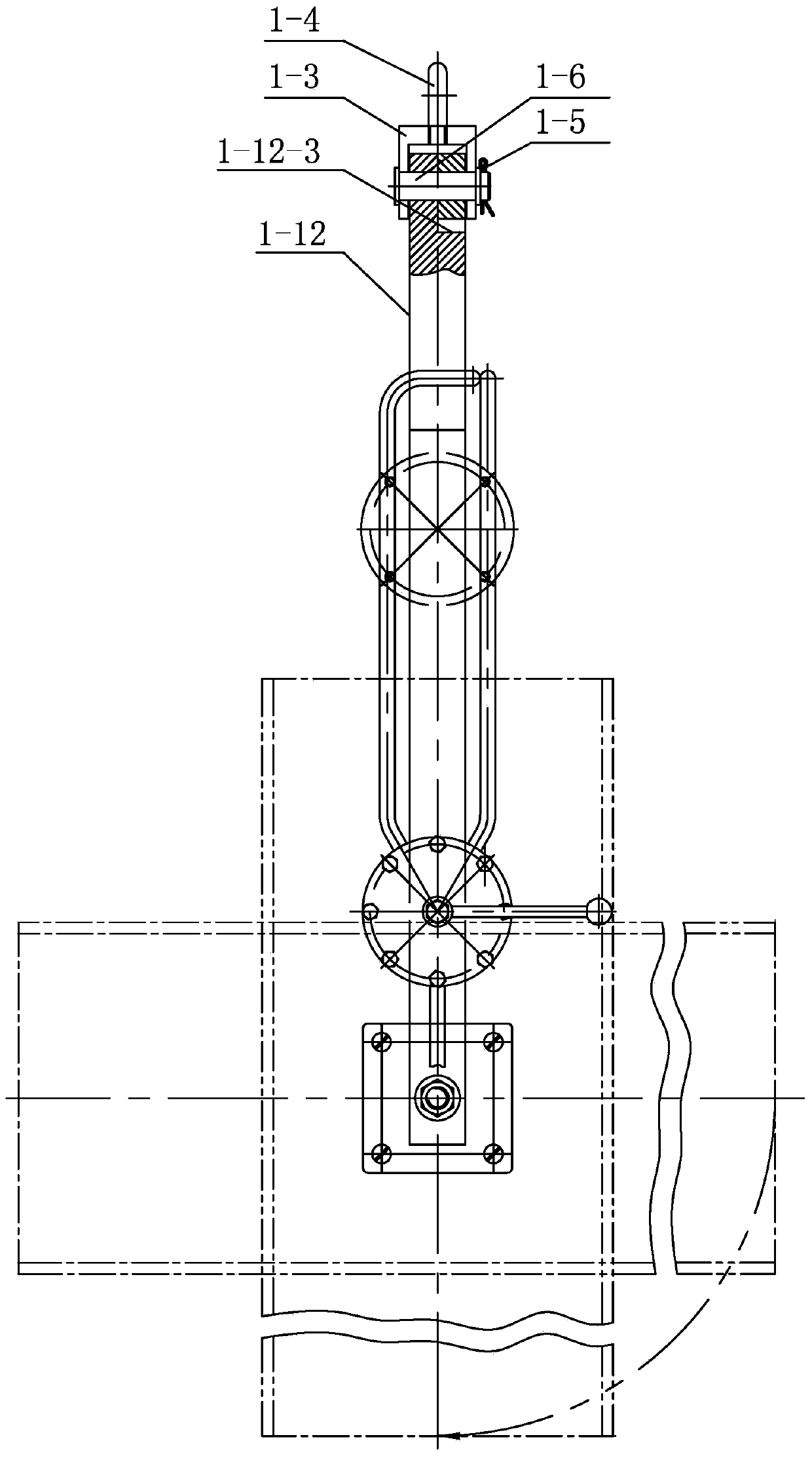
[0025] Specific implementation mode one: as Figure 1 to Figure 6 , Figure 10 ~ Figure 14 As shown, the heated steel pipe is hoisted and turned over by its own weight, which includes a clamping frame assembly 1, a pneumatic mechanism assembly 3 and two clamping head assemblies 2; the clamping frame assembly 1 includes a gas distribution valve seat 1-1, a cylinder seat 1-2, clamping arm connecting seat 1-3, lifting ring 1-4, clamping arm shaft 1-6, connecting sleeve 1-8, connecting sleeve 1-9 and two clamping arms 1-12; pneumatic mechanism Component 3 includes air source conduit 3-1, gas reversing valve 3-2, cylinder left air guide pipe 3-4, cylinder right air guide pipe 3-5 and cylinder 3-6;
[0026] Two clamping arms 1-12 are all made of vertical arm and oblique arm, and the upper end of vertical arm is connected with the lower end of oblique arm, and the arm length of oblique arm is shorter than the arm length of vertical arm; Two clamping arms 1 -12 is arranged relative ...
specific Embodiment approach 2
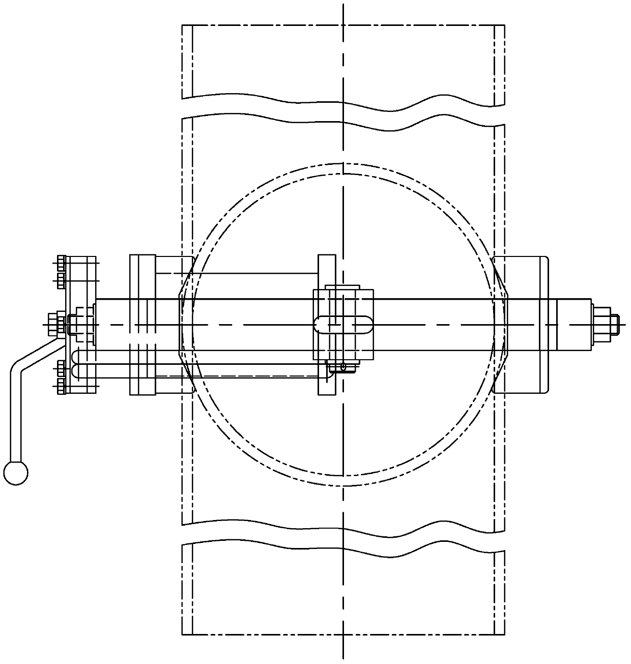
[0027] Specific implementation mode two: as figure 1 , Figure 7 ~ Figure 9 As shown in the specific embodiment 1, the heating steel pipe lifting self-weight flipping pneumatic clamper described in the first embodiment, the two clamping head assemblies 2 both include a clamping head 2-1, a bearing cover 2-2, and a sleeve 2-3 , bearing 2-4, nut 2-6 and clamping head shaft 2-8; the cross section of clamping head 2-1 is rectangular, the middle part of clamping head 2-1 is provided with a shoulder hole, and the outer part of bearing 2-4 The ring is installed in the shoulder hole of the clamping head 2-1, one end face of the clamping head 2-1 is detachably connected with the bearing cap 2-2 by screws, and the processing of the other end face of the clamping head 2-1 There are two trapezoidal grooves 2-1-1, and the two trapezoidal grooves 2-1-1 are arranged in a cross; that is, the two trapezoidal grooves 2-1-1 of the clamping head 2-1 are separately arranged on the clamping head 2...
specific Embodiment approach 3
[0028] Specific implementation mode three: as Figure 4 As shown in the specific embodiment 1 or 2, for the heated steel pipe hoisting self-weight flipping pneumatic clamper, the angle formed between the oblique arm and the vertical arm of the clamping arm 1-12 is α, α=135 °. The effect is to keep the left and right vertical arms parallel to each other in the state of clamping the workpiece.
PUM
 Abstract
Description
Claims
Application Information
 - R&D Engineer
- R&D Manager
- IP Professional
- Industry Leading Data Capabilities
- Powerful AI technology
- Patent DNA Extraction
Browse by: Latest US Patents, China's latest patents, Technical Efficacy Thesaurus, Application Domain, Technology Topic, Popular Technical Reports.
© 2024 PatSnap. All rights reserved.Legal|Privacy policy|Modern Slavery Act Transparency Statement|Sitemap|About US| Contact US: help@patsnap.com