Image forming apparatus and image forming control method
A technology of the image and control unit, which is applied to the printing device, printing, etc., can solve the problems of printing quality degradation, no correction medium, etc., and achieve the effect of suppressing skew
- Summary
- Abstract
- Description
- Claims
- Application Information
AI Technical Summary
Problems solved by technology
Method used
Image
Examples
Embodiment approach 1
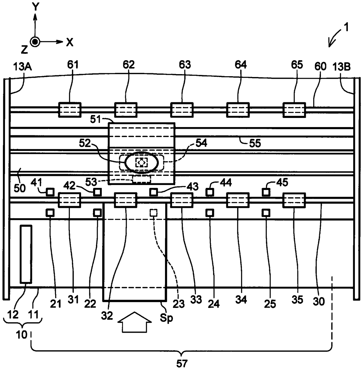
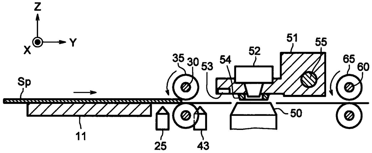
[0047] figure 1 is a diagram schematically showing main mechanisms of the image forming apparatus 1 according to Embodiment 1 of the present invention, figure 2 is viewed from the side figure 1 The mechanism is shown in the diagram. figure 1 and figure 2 The shown X-axis, Y-axis, and Z-axis are perpendicular to each other. The image forming apparatus 1 of the present embodiment has a height in the positive direction of the Z axis, a width in the direction of the X axis, and a depth in the positive direction of the Y axis.
[0048] Such as figure 1 and figure 2 As shown, the image forming apparatus 1 has: side frames 13A, 13B; a space carriage 51 arranged to scan freely in the main scanning direction (X-axis direction); a printing head as a printing part (print recording head) 52 mounted on the space carriage 51; a platen 50 disposed opposite to the print head 52; a table 11 as a medium mounting portion for setting a sheet-shaped to-be-printed medium Sp; a medium s...
Embodiment approach 2
[0127] Next, Embodiment 2 of the present invention will be described. Figure 24 is a diagram schematically showing main mechanisms of the image forming apparatus 2 according to Embodiment 2, Figure 25 is viewed from the side Figure 24 The mechanism is shown in the diagram. Figure 24 and Figure 25 The shown X-axis, Y-axis, and Z-axis are perpendicular to each other.
[0128] Such as Figure 24 and Figure 25 As shown, the image forming apparatus 2 of this embodiment has: a gap lever (gap adjustment mechanism) 67, which is used to adjust the gap interval between the print head 52 and the platen 50 in stages according to the thickness of the medium Sp to be printed; and A gap detection sensor 68 (eg, a transmissive sensor) optically detects the gap interval. Figure 24 and Figure 25 The mechanically acting mechanism shown has the same figure 1 and figure 2 The mechanism shown is the same, but also has a gap lever 67 and a gap detection sensor 68 .
[0129] The c...
PUM
 Abstract
Description
Claims
Application Information
 - R&D
- Intellectual Property
- Life Sciences
- Materials
- Tech Scout
- Unparalleled Data Quality
- Higher Quality Content
- 60% Fewer Hallucinations
Browse by: Latest US Patents, China's latest patents, Technical Efficacy Thesaurus, Application Domain, Technology Topic, Popular Technical Reports.
© 2025 PatSnap. All rights reserved.Legal|Privacy policy|Modern Slavery Act Transparency Statement|Sitemap|About US| Contact US: help@patsnap.com


