
An electrode adapter device for bioimpedance measurement

A switching device, bioimpedance technology, which is applied in the directions of diagnostic recording/measurement, application, medical science, etc., can solve the problems of test error, poor crimping of electrode points, large randomness of coupling value between lines, etc., to ensure reliable consistency and consistency, eliminating uncertainty, and ensuring the effect of consistency

Active Publication Date: 2019-05-28
SEALAND TECH CHENGDU
View PDF7 Cites 0 Cited by
  • Summary
  • Abstract
  • Description
  • Claims
  • Application Information

AI Technical Summary

Problems solved by technology

Through actual application, it is found that the replaceable electrodes made by flexible wire connection have a large randomness in the coupling value between the lines each time they are made, and the stray capacitance value cannot be determined, which leads to the inconsistency of the calibration parameters, and it is difficult to ensure the consistency of the test results. Accuracy; and the hard crimping method is through the crimping between the measuring electrode and the front-end contact of the excitation acquisition circuit. This method has a good initial effect, but with the increase in the number of uses, the wear of the lock may cause the pressure of a certain electrode point. Inaccurate connections cause test errors, and the contact positioning of the measuring electrodes is required to be extremely accurate, otherwise it may not be able to be connected accurately due to positional deviations

Method used


Image

  • An electrode adapter device for bioimpedance measurement
  • An electrode adapter device for bioimpedance measurement
  • An electrode adapter device for bioimpedance measurement

Examples


Embodiment 1

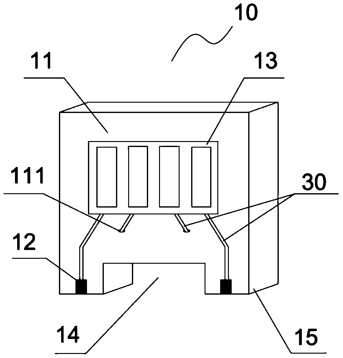
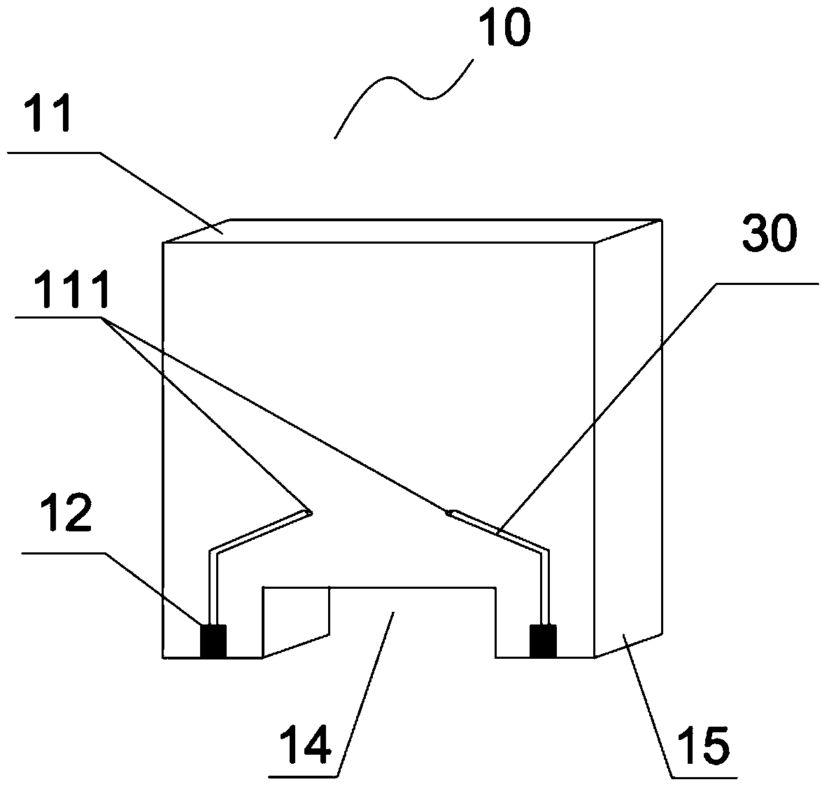
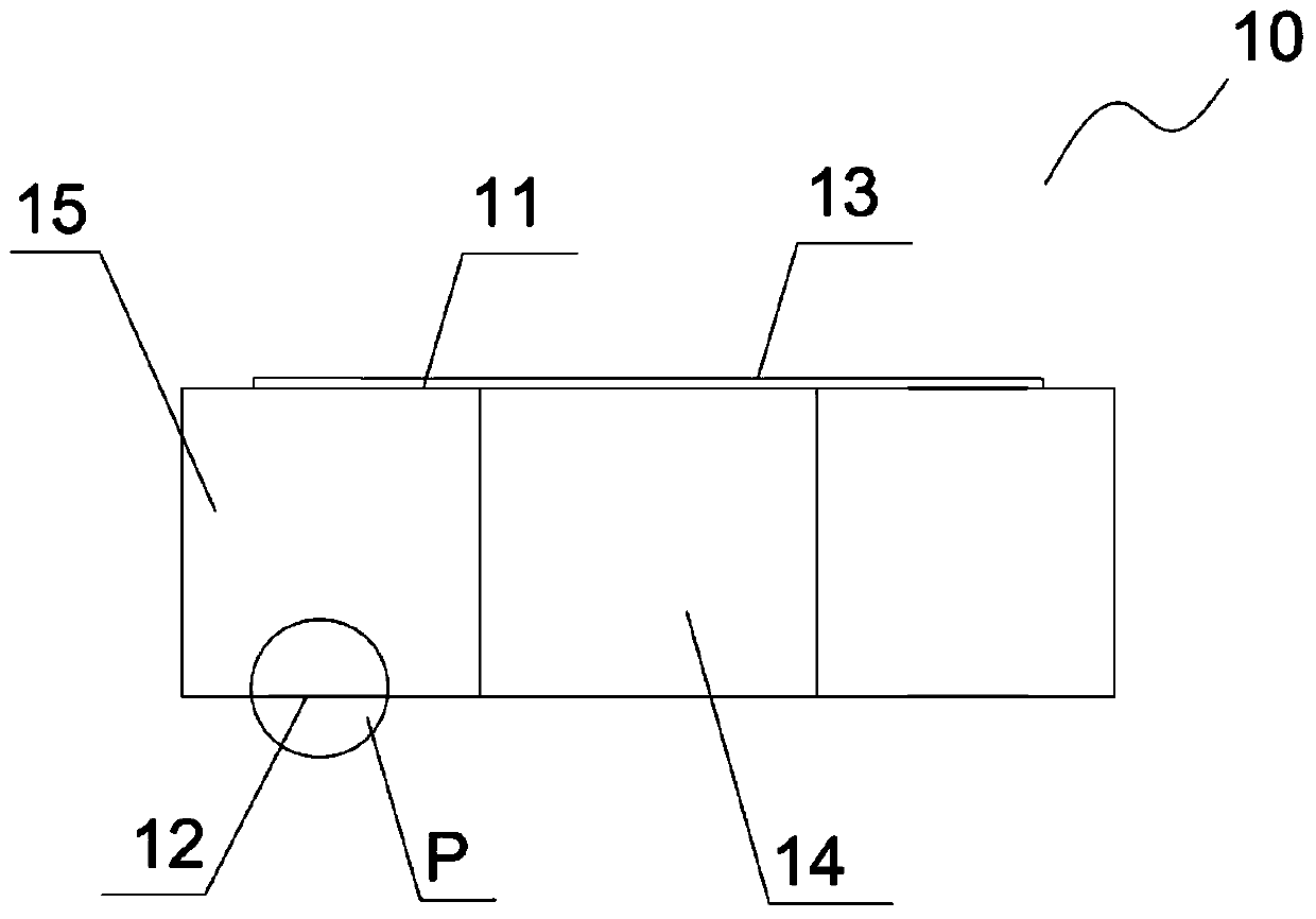
[0036] Such as Figure 1 to Figure 4 As shown, the embodiment of the present invention provides an adapter plate 10 for bio-impedance measurement, including an adapter plate body 11, a first adapter pad 12 installed on the adapter plate body 11 and an electrical connection device 13; the adapter plate body 11 includes a contact portion 15 extending outward from both sides of the bottom of the adapter plate body 11 and a hollow gap 14 between the contact portions 15; the first transfer welding The disk 12 is electrically connected to the electrical connector 13 through the first microstrip line 30 .

[0037] The first transfer pads 12 are arranged symmetrically on both sides of the contact portion 15 to ensure the reliability of the connection between the transfer board and the external test device and the consistency of signal transmission.

[0038] In order to correspond conveniently to the position of the measuring electrodes on the external test device, the shape of the ad...

Embodiment 2

[0042] Since the existing technology generally adopts two methods of direct crimping and soft connection between the measuring electrode and the excitation acquisition circuit, but if the direct crimping method is used, the size of the transfer pad will be limited by the size of the measuring electrode plate, and the electrode plate is required to be transferred. The positioning of the connecting pad must be accurate, otherwise it may be connected incorrectly; if the soft connection method is used, the difference in the winding method of each cable will cause different inter-line coupling values, and there will be a large stray capacitance, which will cause mass production. Time consistency is poor. In view of this, the present invention proposes the following new technical solution that does not limit the size of the electrode plate and the arrangement of the measuring electrodes.

[0043] Such as Figure 5 to Figure 7 As shown, the present invention also provides an electrode...

Embodiment 3

[0048] refer to Figures 8 to 10 As shown, the biggest difference between the embodiment of the present invention and the above-mentioned embodiment 2 is that the electrode plate 20 includes an electrode plate body 21, and multiple rectangular arrays located below the hollow gap 14 of the adapter plate body 11. Each measuring electrode 22 is electrically connected to the measuring electrodes 22 through the second microstrip line 30 ′ in one-to-one correspondence with the second transfer pad 23 . Other structures are the same as those in Embodiment 2 above, and will not be repeated here.

[0049] According to Embodiments 2 and 3 of the present invention, the electrode transfer device mainly uses vertical pressure welding between the first transfer pad and the second transfer pad, which not only ensures the consistency of the connection, but also facilitates The measurement electrode test arranged in a straight line or square shape on the electrode plate eliminates the uncertai...


PUM


Abstract

The invention belongs to the field of bio-impedance measurement equipment, and particularly discloses a switching board for bio-impedance measurement and an electrode switching device. The switching board comprises a switching board body, a first switching bonding pad and an electric connector, wherein the first switching bonding pad is arranged on the switching board body, the switching board body comprises contact parts and a hollow notch, the contact parts are formed by outwards extending from the two sides of the bottom of the switching board body, the hollow notch is positioned between the contact parts, and the first switching bonding pad is electrically connected with the electric connector through a first microstrip line. The invention also discloses a switching device, which comprises the switching board and an electrode board, wherein the switching board and the electrode board are in hard connection. The measuring electrode consistency can be ensured, the uncertainty in each time of processing when soft connection is adopted in the prior art is avoided, the calibration parameter is universal, the single calibration in each time is not needed, the processing precision requirement of the used electrode board is also reduced, and the processing cost is also reduced.

Description

technical field [0001] The invention belongs to the field of biological impedance measurement equipment, and in particular relates to an electrode adapter device for biological impedance measurement. Background technique [0002] In bio-impedance measurement, when conventional PCB board thickness is usually used, the distribution of measurement electrodes is limited to a "one"-shaped arrangement, that is, a straight line, to ensure the hard connection between the measurement electrodes on the probe and the front end of the excitation acquisition circuit; Sometimes, in order to realize the hard connection between the measurement electrodes and the front end of the excitation acquisition circuit in a rectangular arrangement or in other ways, the PCB board is generally thickened, but the size of the measurement electrode surface and the distance between the measurement electrodes are greatly limited. [0003] To avoid cross-contamination of test subjects, the measuring electrod...

Claims


Application Information

Patent Timeline
Patent Type & Authority Patents(China)
IPC IPC(8): A61B5/053
Inventor 张亮徐现红戴涛向飞蒲洋高松卜力宁
Owner SEALAND TECH CHENGDU
Learn More