Energy-saving micro-consumption standby power source and Energy-saving micro-consumption timing remote control switch

A standby power supply and timing controller technology, applied in electronic switches, electrical components, pulse technology, etc., can solve the problems of many display devices, large standby current consumption, instability and unreliability, and achieve narrow discharge pulses and avoid reverse Breakdown, the effect of improving stability and reliability

Inactive Publication Date: 2014-12-10
刘敢
View PDF5 Cites 0 Cited by
  • Summary
  • Abstract
  • Description
  • Claims
  • Application Information

AI Technical Summary

Problems solved by technology

[0003] The purpose of the present invention is to provide an energy-saving and low-consumption standby power supply and a timing remote control switch to solve the problems in the prior art that the standby current consumption is large, unstable and unreliable, there are many display devices, and the control fails due to excessive standby

Method used


Image

  • Energy-saving micro-consumption standby power source and Energy-saving micro-consumption timing remote control switch
  • Energy-saving micro-consumption standby power source and Energy-saving micro-consumption timing remote control switch
  • Energy-saving micro-consumption standby power source and Energy-saving micro-consumption timing remote control switch

Examples


Embodiment Construction

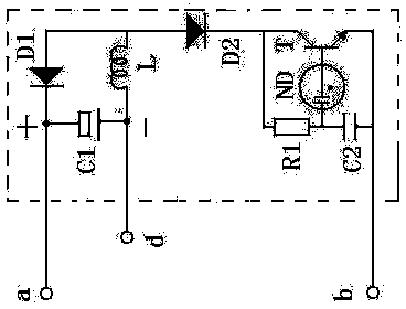
[0015] see figure 1 , the embodiment of the energy-saving and low-consumption standby power supply includes a capacitor C1, a capacitor C2, a resistor R1, an inductor L, a diode D1, a diode D2, a triode T, and a neon lamp ND. The negative pole of the diode D1 is connected to the positive pole of the capacitor C1, and the capacitor C1 The negative pole is connected to one end of the inductor L, the other end of the inductor is connected to the positive pole of the diode D1 and connected to the positive pole of the diode D2, the negative pole of the diode D2 is connected to one end of the resistor R1 and connected to the collector of the transistor T, and the other end of the resistor R1 One end of the capacitor C2 is connected with one end of the neon lamp ND, the other end of the neon lamp ND is connected with the base of the transistor T, and the emitter of the transistor T is connected with the other end of the capacitor C2.

[0016] The working principle of this embodimen...


PUM


Abstract

The invention relates to an energy-saving micro-consumption standby power source and an energy-saving micro-consumption timing remote control switch. The energy-saving micro-consumption timing remote control switch comprises the energy-saving micro-consumption standby power source, and a microcomputer timing controller, a receiver and an indicating neon lamp are arranged in the energy-saving micro-consumption timing remote control switch. The energy-saving micro-consumption standby power source and the energy-saving micro-consumption timing remote control switch have the following advantages: based on the characteristics of narrow discharge pulse and extremely low power consumption of the inert gas neon, an induced current is generated by virtue of ionic discharge of the neon in combination with an amplifying triode and an inductor and used for supplying power for the microcomputer timing controller so as to obtain more tiny current from a main power supply circuit, and therefore, the power consumption is further reduced and the standby current consumption of the electronic controller is further reduced; as a diode is connected in series with the collector of the triode for one-way rectification, reverse breakdown of the triode is avoided and the stability and the reliability of the switch in the standby mode are greatly improved; the coordination between the microcomputer timing controller and a load and the neon lamp is taken as timing indication so that the cost of a display device and the current consumption of the display device can be reduced, and furthermore, the display device can be well applied to the control occasion requesting extremely low standby current, and the energy saving efficiency is further improved.

Description

technical field [0001] The invention relates to an energy-saving and low-consumption standby power supply and a timing remote control switch, which are mainly used for electronic control of electric appliances. Background technique [0002] The existing electronically controlled standby power supply generally adopts a transformer or capacitor step-down method to obtain the standby voltage and current, which has the problem of large standby current consumption, and also uses an energy-saving circuit to obtain the standby voltage and standby current, but there is stability. and reliability issues, in addition, the existing timing switch needs to use a digital tube or a combination of multiple indicator lights to display the length of the timing time, the disadvantage is that the digital display and both need to increase the display device and increase the necessary display current. Waste of materials and waste of electric energy, especially for circuit control occasions that r...

Claims


Application Information

Patent Timeline
Patent Type & Authority Applications(China)
IPC IPC(8): H03K17/28
Inventor 刘敢
Owner 刘敢
Why Eureka
Try Eureka