
Solar steady persistence lighting system and excitation method thereof

A technology of long afterglow luminescence and long afterglow illuminator, applied in electroluminescence light source, control/regulation system, light source and other directions, can solve the problems of unsuitable installation of solar panels, too large, high product cost, and achieve broad market prospects and The effect of social benefit

Active Publication Date: 2014-12-10
ZHEJIANG MINGHUI LUMINESCENCE TECH CO LTD
View PDF7 Cites 12 Cited by
  • Summary
  • Abstract
  • Description
  • Claims
  • Application Information

AI Technical Summary

Problems solved by technology

At present, the area of ​​solar cells is 110W / m2, and the power of a 10cm*10cm solar panel is only 1.1W. In addition, due to the influence of climate (weather) and the limitation of geographical location, ordinary solar light-emitting devices are generally difficult Ensure that the light device continues to emit relatively strong light throughout the night
In order to solve this problem, larger solar panels are generally used as much as possible, but too large solar panels lead to high product costs; in addition, some light-emitting devices are limited by the installation location and conditions, so it is not suitable to install too large solar panels. solar panel

Method used


Image

  • Solar steady persistence lighting system and excitation method thereof
  • Solar steady persistence lighting system and excitation method thereof
  • Solar steady persistence lighting system and excitation method thereof

Examples


Embodiment Construction

[0059] Examples of specific implementation methods:

[0060] 1. A solar long afterglow light strip:

[0061] As shown in Figure 4:

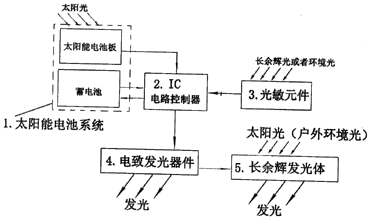
[0062] 1. Solar battery system: solar panels and batteries.

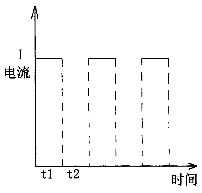
[0063] 2. IC controller: When the photosensitive element perceives that the ambient illuminance is lower than 10lx, the IC controller receives the signal from the photosensitive element, and the IC controls the electroluminescent device to start working. The electroluminescent device works for 2 minutes and stops for 15 minutes, so The cycle is repeated; when the photosensitive element perceives that the ambient illuminance is greater than 10lx, the IC controls the electroluminescent device to stop working completely.

[0064] 3. Photosensitive control element: set the trigger point parameter of the photosensitive control element to 10lx (environmental light illuminance value).

[0065] 4. Electroluminescent devices: LED light emitting devices that emit blue-violet light.

[0066] ...


PUM


Abstract

A solar steady persistence lighting system comprises a solar cell system (1), an IC (integrated circuit) controller (2), a photosensitive control element (3) and electroluminescent devices (4). One or more electroluminescent devices (4) are arranged around or inside every steady persistence light emitter (5) and connected and mounted with the IC controller (2) through a line, and the IC controller (2) is connected and mounted with the solar cell system (1) and the photosensitive control element (3) respectively through lines. An excitation method of the solar steady persistence lighting system is characterized in that the IC controller receives a signal of a photosensitive element when the photosensitive element which is under the control of the IC controller senses that the ambient light illumination is smaller than a set illuminance value, the IC controller controls the electroluminescent device to start working, the electroluminescent device stops emitting light for set stop time after emitting light for set light-emitting time, and the above process is recycled. The IC controller controls the electroluminescent device to completely stop working when the photosensitive element senses that the ambient light illumination is larger than the set illuminance value. According to the solar steady persistence lighting system and the excitation method thereof, the uncontrollable luminance of the steady persistence light emitters can be artificially controlled, and the luminance of a product can be designed as needed.

Description

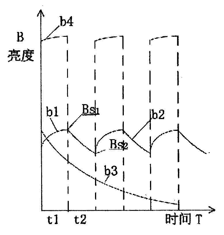
technical field [0001] The invention relates to a long afterglow light emitting system with solar energy, in particular to a long afterglow light emitting system with solar energy and an excitation method thereof. Background technique [0002] Long afterglow material is a light-storage photoluminescent material. When it is excited by light for a certain period of time and at a certain intensity, it will continue to emit light after the excitation stops. The process of its continuous luminous intensity gradually decreasing from high to low called afterglow. Its luminescence curve is a superposition of a negative exponential function and a hyperbolic function. After the excitation is stopped, the shorter the time, the higher the brightness, and the longer the time, the lower the brightness. [0003] Solar energy refers to the use of sunlight for power generation (or heating) to provide energy. Among them, solar power generation, which has been widely used at present, uses pho...

Claims


Application Information

Patent Timeline
IPC IPC(8): G05D25/02H05B44/00
CPCH02J7/35G05D25/02H05B45/10H05B45/00Y02B20/30
Inventor 方显峰徐林元
Owner ZHEJIANG MINGHUI LUMINESCENCE TECH CO LTD
Learn More