an antenna

An antenna and antenna arm technology, applied to antennas, folded antennas, electrical components, etc., can solve the problems of large changes in the position of the center of gravity, reduced system reliability, poor system rigidity, etc., and achieves compact dimensions and tight space layout. , the effect of reducing the moment of inertia

Active Publication Date: 2017-02-01
钟鸣 +1
View PDF5 Cites 0 Cited by
  • Summary
  • Abstract
  • Description
  • Claims
  • Application Information

AI Technical Summary

Problems solved by technology

The above several mechanisms have different technical advantages but also have their own problems. For example, the position of the center of gravity of the turning mechanism and the folding arm mechanism changes greatly under the working conditions of folding and unfolding; The lower center of gravity does not change much, but there is a disadvantage of poor rigidity of the system. If the above mechanisms are combined, it will cause complex mechanisms, many driving components, and reduced system reliability.

Method used


Image

  • an antenna
  • an antenna
  • an antenna

Examples


Embodiment Construction

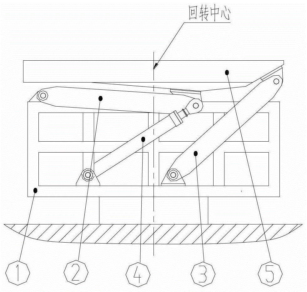
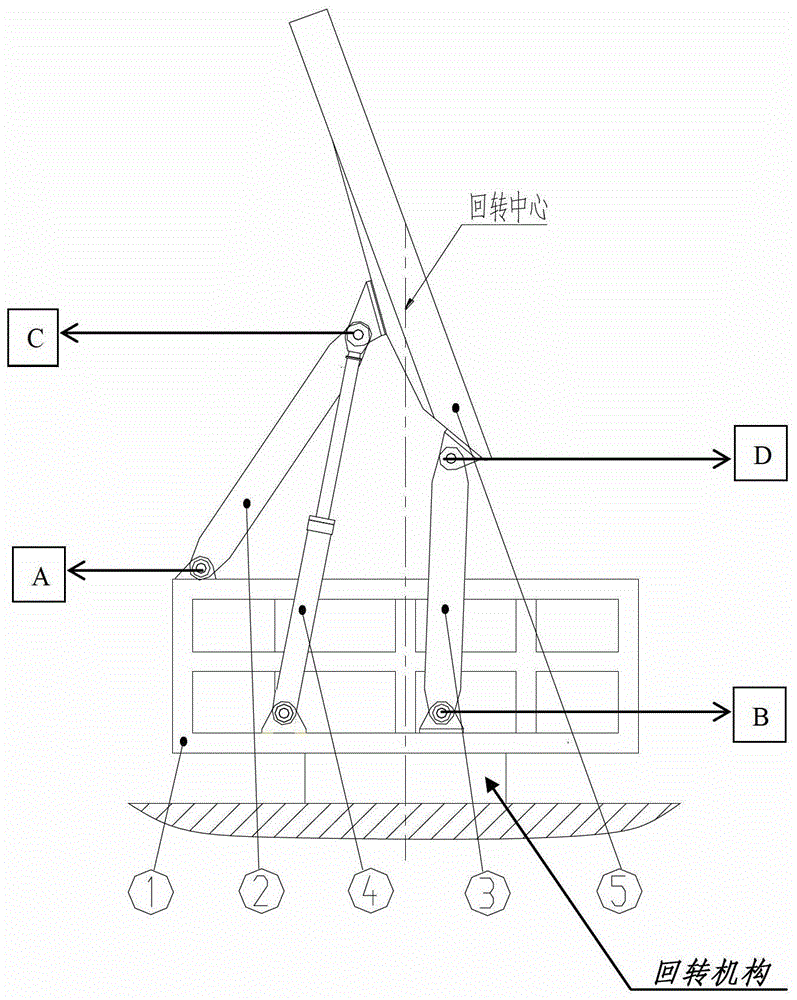
[0024] Such as figure 1 , figure 2 As shown, an antenna provided by the present invention is a component for radiating or receiving radio waves, including a transmitter, a receiver, a transmission line, a frame 1, a driving rod 2, a driven rod 3, a driving cylinder 4, and an antenna Boom 5.

[0025] The antenna provided by the invention receives radio waves through the receiver; at the same time, the transmitter can transmit signals to the outside; the transmitter and the receiver perform signal transmission through the transmission line.

[0026] Among them, the frame 1, the driving rod 2, the driven rod 3, the driving cylinder 4 and the antenna arm frame 5 are hinged to form a linkage mechanism, and the driving cylinder 4 is the driving element; the frame 1 is a rigid frame structure welded by steel plates Or a closed box-shaped structure, which is arranged on the slewing mechanism, and the lower hinge point of the driving rod 2, the lower hinge point of the driven rod 3 ...


PUM


Abstract

The invention discloses an antenna which comprises the components of: a transmitter, a receiver, a transmission line, a frame 1, a support member and an antenna boom 5. An improvement of the antenna is characterized in that: the frame 1 is arranged on a rotating mechanism and rotates around a center axis of the rotating mechanism; the support member comprises a driving rod 2, a driven rod 3 and a driving cylinder 4. Two ends of the driving rod 2 are respectively connected with the frame 1 and the antenna boom 5. One end of the driving cylinder 4 is connected with the frame 1, and the other end is arranged at a connecting point between the driving rod 2 and the antenna boom 5. The connecting point is arranged between the middle part and the tail part of the antenna boom 5. One end of the driven rod 3 is connected with the frame 1, and the other end is connected with the tail part of the antenna boom 5. The driving rod 2 and the driven rod 3 are driven to overturn through the driving cylinder 4. Furthermore the antenna boom 5 is folded or expanded. The antenna ensures no gravity center position change of the antenna in the horizontal direction in the folded state and the expanded state of the antenna. The antenna has advantages of: simple structure, high rigidity, small number of driving elements, high system reliability, and compact appearance dimension in the folded state. The antenna is particularly suitable for on-vehicle equipment.

Description

technical field [0001] The invention relates to an antenna, in particular to an antenna used on a vehicle, and belongs to the technical field of vehicle accessories. Background technique [0002] With the vigorous development of national defense technology in our country, higher requirements are put forward for the maneuverability of communication, radar and other electronic equipment. The equipment is often designed in a vehicle-mounted form, so the antenna lifting and erecting mechanism is required to realize the following functions: lift the electronic equipment to a certain height and pitch angle in its working state, and fold the antenna to meet the general-purpose requirements under driving conditions. The dimension requirements of road regulations for length, width and height. At present, there are the following kinds of antenna deployment and retraction mechanisms at home and abroad: 1. Turning mechanism: the antenna boom is turned around a fixed hinge point; 2. Tel...

Claims


Application Information

Patent Timeline
Patent Type & Authority Patents(China)
IPC IPC(8): H01Q1/08H01Q3/06
Inventor 钟鸣李瑞功
Owner 钟鸣
Why Eureka
Try Eureka