Mechanical transmission device

A technology of mechanical transmission and transmission shaft, which is applied in transmission devices, mechanical equipment, belts/chains/gears, etc., and can solve problems such as inability to use mechanical fuel, troublesome and inconvenient installation of shaft-shaped connections, etc.

Inactive Publication Date: 2014-12-03
邹新鹏
View PDF3 Cites 5 Cited by
  • Summary
  • Abstract
  • Description
  • Claims
  • Application Information

AI Technical Summary

Problems solved by technology

However, the installation of these shaft-shaped connections is quite troublesome, and it cannot fully convert mechanical fuel or mechanical inertia into power for utilization
[0003] Therefore, existing starting device obviously still has inconvenience and defect in structure and use, and urgently needs to be further improved

Method used


Image

  • Mechanical transmission device
  • Mechanical transmission device
  • Mechanical transmission device

Examples


Embodiment 1

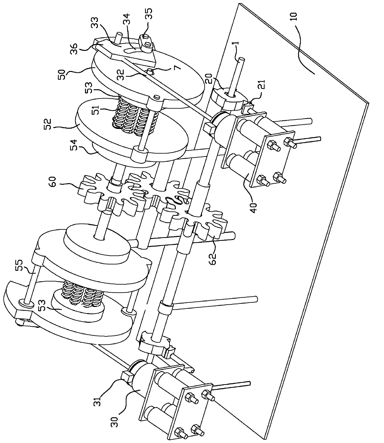
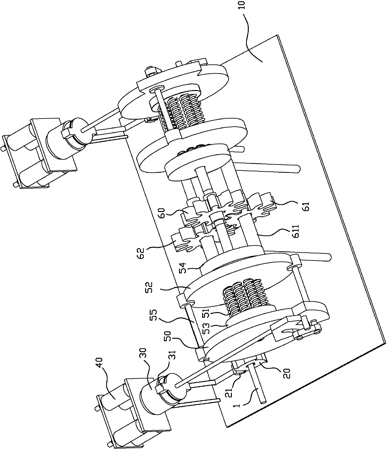
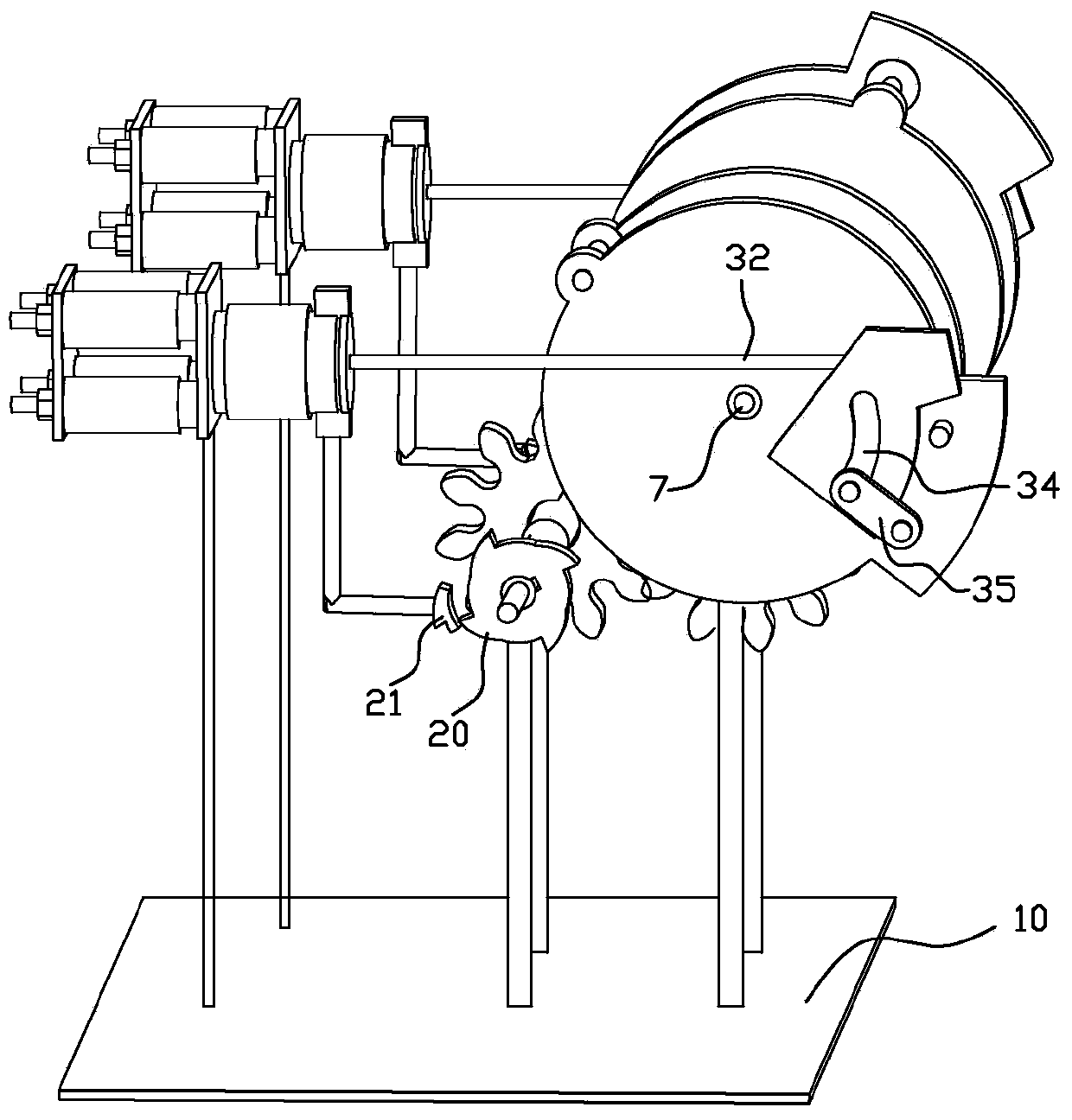
[0038] A kind of mechanical transmission device of the present invention, as Figure 1~3 As shown, the device includes a power generation mechanism, a power release mechanism, a power transition mechanism and a power return mechanism, wherein the power generation mechanism, the power release mechanism and the power transition mechanism are fixed on the base through a connecting rod component.

[0039] The power generating mechanism includes a power device and a connecting cylinder 30, one end of the connecting cylinder 30 is connected to the power device, and the other end is connected to the power release mechanism through a connecting rod assembly, and the end of the connecting cylinder 30 deviated from the power device is provided with two The fixed angles 31 , one of the fixed angles 31 is connected to the power return mechanism through the contraction plate 21 .

[0040] The power release mechanism includes a power output shaft 7, a first gear 60 fixedly sleeved at the ce...


PUM


Abstract

The invention relates to a mechanical transmission device. The device comprises a power generation mechanism, a power releasing mechanism, a power transition mechanism and a power back-transmission mechanism, wherein the power generation mechanism comprises a power device and a connecting cylinder; the power releasing mechanism comprises a power output shaft, a first gear and elastic transmission assemblies arranged on two sides of the first gear, the elastic transmission assemblies are provided with connecting rod assemblies connected with the connecting cylinder, the connecting rod assemblies can drive driving wheel assemblies to rotate on the power output shaft, and an angle between each of two push points, by which the two connecting rod assemblies are connected with the driving wheel assemblies for rotation, and the power output shaft is 45 degrees; and the power releasing mechanism transmits power through gears while releasing the power, so that one transmission block of the power back-transmission mechanism is always staggered with an arc angle of the four-angle transmission wheel arranged at the end where the transmission block is located, and performs staggered movement under the pushing of the power device for a next round of transmission. The device has the advantages of novel structure, energy saving, environment protection and improvement of power system efficiency.

Description

technical field [0001] The invention relates to the mechanical field, in particular to a mechanical transmission device. Background technique [0002] Currently, gasoline or electric drives are mainly used for driving mechanical equipment. Due to the deteriorating environment caused by the emission of waste during the use of gasoline, the depletion of petroleum resources and the huge fluctuations in petroleum prices, fuel-saving mechanical devices are gradually favored by people. The existing transmission equipment used in the driving device usually has a housing in which some gears are installed and mounting holes are used to pass through the shaft connected with the gears; through these gears, it is possible to realize from an axial direction under the condition that the shaft speed changes. Torque transmission from the other shaft. However, the installation of these shaft-shaped connections is quite cumbersome, and the mechanical fuel or mechanical inertia cannot be ful...

Claims


Application Information

Patent Timeline
Patent Type & Authority Applications(China)
IPC IPC(8): F16H37/12
CPCF16H37/124
Inventor 邹新鹏
Owner 邹新鹏
Why Eureka
Try Eureka