Method and control unit for determining a mass flow in a high-pressure exhaust gas recirculation system of an internal combustion engine

A technology of exhaust gas recirculation and recirculation system, which is used in exhaust gas recirculation, electrical control, engine control, etc., and can solve problems such as inaccurate throttling model

Active Publication Date: 2019-10-01
ROBERT BOSCH GMBH
View PDF12 Cites 0 Cited by
  • Summary
  • Abstract
  • Description
  • Claims
  • Application Information

AI Technical Summary

Problems solved by technology

The throttling model is very inaccurate if the ratio of intake manifold pressure to exhaust backpressure is greater than 0.9

Method used


Image

  • Method and control unit for determining a mass flow in a high-pressure exhaust gas recirculation system of an internal combustion engine
  • Method and control unit for determining a mass flow in a high-pressure exhaust gas recirculation system of an internal combustion engine

Examples


Embodiment Construction

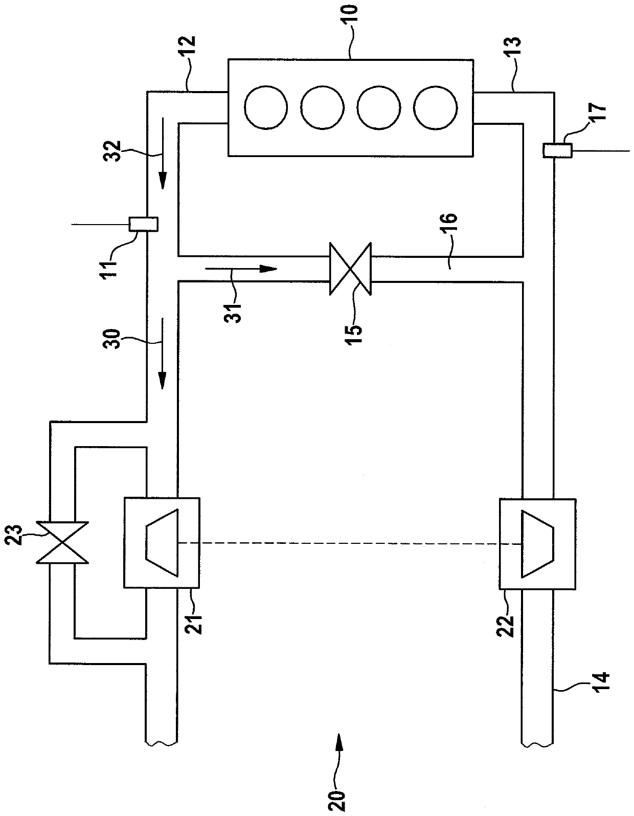
[0028] figure 1 An internal combustion engine 10 with a turbocharger 20 and a high-pressure exhaust gas recirculation system 15 is shown schematically. The illustration is here limited to those components which are essential for the description of the invention. Along the intake duct 14 , fresh air is supplied to the internal combustion engine 10 via the compressor 22 of the turbocharger 20 and the intake line 13 . The intake structure is divided into a low-pressure region upstream of the compressor 22 and a high-pressure region downstream of said compressor 22 in the flow direction. A first pressure sensor 17 is arranged in the intake pipe 13 .

[0029] Exhaust gas from internal combustion engine 10 is discharged from internal combustion engine 10 via exhaust train 12 via exhaust gas turbine 21 of turbocharger 20 and exhaust valve 23 bypassing exhaust gas turbine 21 to an exhaust gas aftertreatment system (not shown). The exhaust gas structure is also divided into a high-p...


PUM


Abstract

The invention relates to a method for determining an exhaust gas recirculation mass flow in a high pressure exhaust gas recirculation system of an internal combustion engine, wherein exhaust gas is discharged from an exhaust line before an exhaust turbine of a turbocharger and passes through a compressor of the turbocharger of the high-pressure exhaust gas recirculation system and then is transmitted to an intake manifold of the internal combustion engine, intake manifold pressure in the intake manifold in front of the internal combustion engine and an exhaust gas back pressure in the exhaust line being behind the internal combustion engine and in the upstream of the high-pressure exhaust gas recirculation system can be determined. It is envisaged that from the intake manifold pressure and an injected fuel mass a total exhaust mass flow is determined, an exhaust gas mass flow through the exhaust turbine of the turbocharger is determined at least from the exhaust back pressure, and the exhaust gas recirculation mass flow is determined from the difference between the total exhaust mass flow and the exhaust gas mass flow through the exhaust turbine. The invention further relates to a control unit for performing the method. The method and the control unit allow the determination of a mass flow of a high-pressure exhaust gas recirculation system of an internal combustion engine.

Description

technical field [0001] The invention relates to a method for determining the mass flow of exhaust gas recirculation in a high-pressure exhaust gas recirculation system of an internal combustion engine, wherein the exhaust gas in the exhaust system is captured upstream of the exhaust gas turbine of the turbocharger and passed through the The high-pressure exhaust gas recirculation system feeds the intake manifold of the internal combustion engine after the compressor of the turbocharger, and wherein the intake manifold pressures in the intake manifold upstream of the internal combustion engine and downstream of the internal combustion engine are determined and Exhaust gas counterpressure in the exhaust system upstream of the high-pressure exhaust gas recirculation system. [0002] Furthermore, the invention relates to a control unit of an internal combustion engine for determining an exhaust gas recirculation mass flow in a high-pressure exhaust gas recirculation system of the ...

Claims


Application Information

Patent Timeline
Patent Type & Authority Patents(China)
IPC IPC(8): F02M26/05F02M26/47F02D21/08F02D23/02
CPCF02B37/18F02D21/08F02D41/0007F02D41/0072F02D41/1445F02D41/1448F02D41/18F02D2200/0402F02D2200/0406F02M26/05F02M26/10F02M26/47Y02T10/40
Inventor M.胡贝尔A.沃尔夫
Owner ROBERT BOSCH GMBH
Why Eureka
Try Eureka