
Inverted V-shaped plate sedimentation device

A technology of sedimentation device and wing plate, applied in the direction of sedimentation tank, etc., can solve the problems of large space occupied by water inlet and outlet, affecting sedimentation effect, increasing sedimentation load, etc., achieving adjustable tank height, good sedimentation effect, and buffering of inlet and outlet water. area reduction effect

Inactive Publication Date: 2014-12-03
YANGZHOU UNIV
View PDF4 Cites 3 Cited by
  • Summary
  • Abstract
  • Description
  • Claims
  • Application Information

AI Technical Summary

Problems solved by technology

There are three disadvantages in the inclined tube sedimentation tank. First, the water and the sludge interfere with each other, which affects the sedimentation effect. The water enters the inclined tube from the bottom up, and the sludge slides downward from the inclined tube. The two collide together and partially settle The mud is washed up by the incoming water and then enters the water, which increases the sedimentation load; second, the height of the tank body is large, and it is not easy to connect with the front and rear treatment structures. Area 1.5m, inclined pipe area 0.87m, clear water area 1~1.2m, super height 0.3m, total height 4.27~4.87m. The height of the pool is large and cannot be changed arbitrarily, so it is not easy to connect; third, the ineffective volume is large. In the total height of the pool body, the height of the inclined pipe area actually used for sedimentation is only 0.87m, and the water inlet and outlet areas take up a lot of space. The total residence time reaches 0.7~0.8h

Method used


Image

  • Inverted V-shaped plate sedimentation device
  • Inverted V-shaped plate sedimentation device
  • Inverted V-shaped plate sedimentation device

Examples


Embodiment Construction

[0018] The present invention is further described in conjunction with the accompanying drawings and examples.

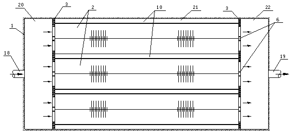
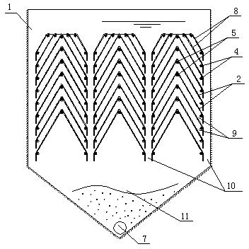
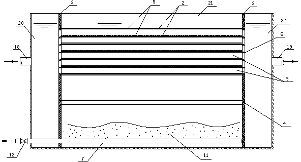
[0019] The inverted V-shaped plate sedimentation device is composed of a pool 1 and an inverted V-shaped plate 2 installed in the pool, a sealing plate 3, a side beam 4, a spine 5, a spine bracket 6, a mud discharge pipe 7, an inlet pipe 18, and an outlet pipe 19. . The plane of the pool 1 is rectangular, the side walls are upright, and the bottom is conical. One end of the pool wall is provided with a water inlet pipe 18, and the other end of the pool wall is provided with an outlet pipe 19. Two sealing plates 3 are used to divide the pool 1 into a water inlet area 20 , a sedimentation area 21 and a water outlet area 22 .

[0020] The two sides and the bottom edge of the sealing plate are fixed with the pool wall.

[0021] An inverted V-shaped plate 2 is set in the precipitation area 21 between the two sealing plates 3, the inverted V-shaped plate 2 is perpendicu...


PUM

PropertyMeasurementUnit
Angleaaaaaaaaaa

Abstract

The invention discloses an inverted V-shaped plate sedimentation device which is a device for sedimentating and separating solid particles in liquid. The inverted V-shaped plate sedimentation device consists of a water basin, and inverted V-shaped plates, sealing plates, edge beams, ridges, ridge brackets, a sludge discharging pipe, a water inlet pipe, a water outlet pipe and the like which are arranged in the water basin, wherein a plurality of layers of horizontally stacked inverted V-shaped plates are adopted; liquid flows among the inverted V-shaped plates; the solid particles are sedimentated on the surfaces of the inverted V-shaped plates and downwards slide laterally so as to realize solid-liquid separation; the liquid horizontally flows along the longitudinal direction, and the sedimentated solid particles downwards slide transversely and stay in sludge sedimentation channels for sedimentation; the solid particles and the sludge sedimentation channels are not interfered, so that the sedimentation effect is good; water inlet and outlet buffering regions are greatly reduced; the volume utilization efficiency of the basin body is high, and the water basin is small in size; the inverted V-shaped plates are simple in structure; the number of stacking layers can be randomly adjusted, and the inverted V-shaped plates are easily connected with front and back buildings.

Description

technical field [0001] The invention relates to a device for precipitating and separating solid particles in liquid, in particular to an inverted V-shaped plate sedimentation and separation device, which adopts multiple layers of inverted V-shaped plates stacked horizontally, and the liquid flows through the layers of the inverted V-shaped plate , solid particles are deposited on the surface of the inverted V-shaped plate to realize solid-liquid separation, which belongs to the field of solid-liquid separation technology, and is suitable for the precipitation and separation of solid particles with a density greater than liquid in water treatment, chemical engineering and other treatment processes. Background technique [0002] In tap water treatment and sewage treatment projects, the sedimentation method is used to remove impurity particles with a density greater than that of water. In chemical engineering, precipitation is also used to separate particles from liquids. The ...

Claims


Application Information

Patent Timeline
IPC IPC(8): B01D21/02
Inventor 丛海兵王巍孙海虎费广武朱飞
Owner YANGZHOU UNIV
Learn More