defensive grappler

A technology of grabbing device and shackles, applied in the field of defense grabbing devices, can solve the problems of poor working safety and reliability of the catching device, slow action response of the shackles, failure of the catching device, etc., and achieves increased work safety and reliability, good overall feeling, Good brake control effect

Inactive Publication Date: 2016-08-17
高航
View PDF7 Cites 0 Cited by
  • Summary
  • Abstract
  • Description
  • Claims
  • Application Information

AI Technical Summary

Problems solved by technology

[0002] The patentee has obtained the patent number: 201020129878, which is called "High Efficiency and Multi-function Defense Grappler". There are fixed racks, which are respectively meshed with the gears fixed on the push-pull rods. The clips are connected into a scissors structure, that is, when the force-applying end is opened, the clips are opened, and the force-applying end is closed to form the clips. The structure is complex and the force is not ideal. The meshing structure of the gear and the rack results in slow response of the shackle action, poor control effect, and heavy weight. Moreover, the machine box adopts a bolt-connected structure. During use, due to impact and other factors, the bolts will loosen, which will cause the grappling device to fail. , the working safety and reliability of the grabber is poor; the clasp is a single-layer structure, and the clamping parts are small when used

Method used


Image

  • defensive grappler
  • defensive grappler
  • defensive grappler

Examples


Embodiment Construction

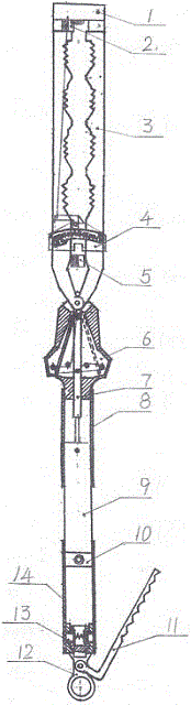
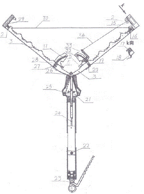
[0039] Such as figure 1 , 2 As shown, the present invention includes a central control box 6, a base plate 46, a front bar 8 fixed to the base plate 46, a middle bar 9 which is sleeved with the front bar 8 to form a sliding connection, and a ratchet rocker 11 connected with the middle bar 9. The base plate 46 is respectively hinged with two left and right handcuffs 3, and the front ends of the handcuffs 3 are two groups of teeth juxtaposed to form the handcuff end, and the upper end of one handcuff 3 is fixed with the upper end of the handcuff lock box 1, and the other handcuff 3 There is a handcuff tooth hook 29 on the upper end, and when the handcuff tooth hook 29 stretches into the handcuff lock box 1, it will be hooked and positioned by the double tooth hook 17 of the lock box, preventing the left and right handcuffs from being opened; The magnet 5, when the left and right handcuffs move to the magnetic force area of ​​the powerful magnet 5, will generate a strong magneti...


PUM


Abstract

Provided is a defensive grappling device. The clamp cuff end and the force exertion end of each clamp cuff are bent towards the same side, and the bending points are coaxial hinge points of the left and right clamp cuffs and a substrate; when a left clamp cuff force exertion end and a right clamp cuff force exertion end are formed and are closed inwards after the left clamp cuff is hinged to the right clamp cuff, the clamp cuff ends are of an outward opening structure; a middle rod is fixedly provided with a push-pull rod, the push-pull rod extends into the substrate and is connected with the substrate to form a sliding structure, and the section, extending into the substrate, of the push-pull rod is provided with four inhaul cable control line fixing ends which are used for fixing end sockets of two inhaul cable control lines; the clamp cuff force exertion ends are provided with pulleys, and each inhaul cable control line is connected with the pulley of one of the clamp cuff force exertion ends, so that when the push-pull rod moves outwards towards the substrate, the inhaul cable control lines drive the clamp cuff force exertion ends to be closed inwards and the clamp cuffs are opened, and when the push-pull rod moves inwards towards the substrate, the inhaul cable control lines 21 drive the clamp cuff force exertion ends to be opened outwards and the clamp cuff ends are clamped closely. The defensive grappling device has the advantages that the structure is simple and practical, the device is well stressed, in the opening or closing process of the clamp cuffs, the formed brake control effect is good, and work safety and reliability are high.

Description

technical field [0001] The invention relates to a high-efficiency, safe and reliable defensive grabbing device with multiple functions to replace human hands to prevent, arrest and control violent people and animals. Background technique [0002] The patentee has obtained the patent number: 201020129878, which is called "High Efficiency and Multi-function Defense Grappler". There are fixed racks, which are respectively meshed with the gears fixed on the push-pull rods. The clips are connected into a scissors structure, that is, when the force-applying end is opened, the clips are opened, and the force-applying end is closed to form the clips. The structure is complex and the force is not ideal. The meshing structure of the gear and the rack results in slow response of the shackle action, poor control effect, and heavy weight. Moreover, the machine box adopts a bolt-connected structure. During use, due to impact and other factors, the bolts will loosen, which will cause the g...

Claims


Application Information

Patent Timeline
Patent Type & Authority Patents(China)
IPC IPC(8): F41B15/00
Inventor 高航
Owner 高航
Why Eureka
Try Eureka