
Novel forging press clutch brake mechanism

A technology of brakes and forging presses, which is applied to the driving device of forging presses, non-mechanical drive clutches, clutches, etc. It can solve the problems of high-speed forging presses, large parts space, and high energy consumption, etc., and achieve rapid combination and separation Reliable, less transmission inertia, overcome the effect of complex structure

Inactive Publication Date: 2014-11-26
XUZHOU LONGTAI COAL MINING EQUIP MFG
View PDF0 Cites 0 Cited by
  • Summary
  • Abstract
  • Description
  • Claims
  • Application Information

AI Technical Summary

Problems solved by technology

The main reason for this is that the existing clutch brakes all use pneumatic friction clutches. This type of clutch brake not only needs compressed air equipment, but at the same time, due to the complex structure of the clutch brake components, the volume of the entire component is relatively large. The inertia is also large, which requires more energy consumption. In addition, because the separation and combination of the clutch are carried out under the control of the mechanical system, and the speed of the mechanical movement is difficult to further increase under certain conditions, so the current There are defects such as complex structure, high energy consumption, slow running speed, troublesome disassembly and assembly, difficult maintenance, low running precision, and inability to meet high-speed forging for clutch brakes.

Method used


Image

  • Novel forging press clutch brake mechanism

Examples


Embodiment Construction

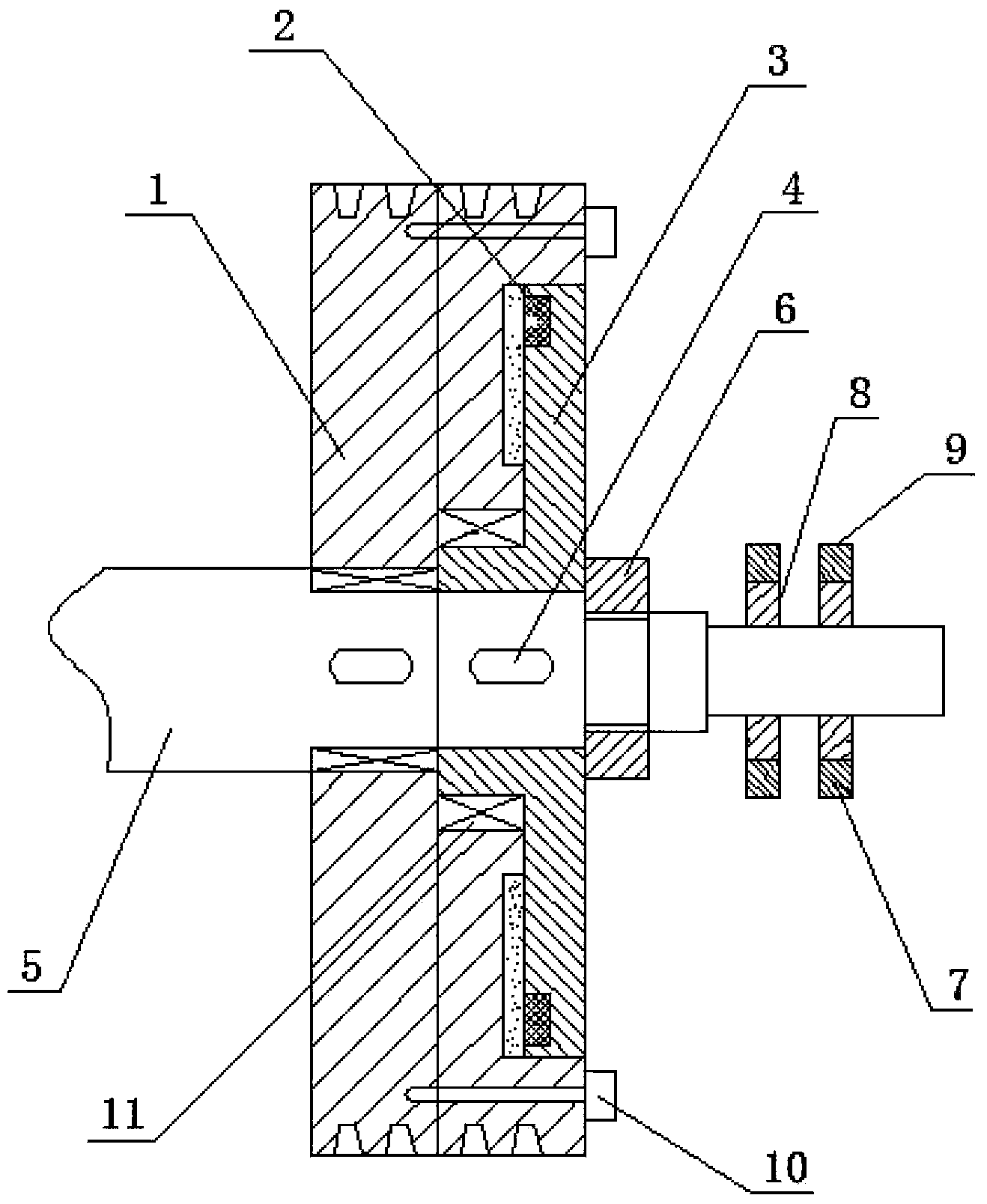
[0010] The clutch brake mechanism has a driving flywheel (1), the driving flywheel (1) is installed on the hollow shaft of the brake driving disc (3) through the positioning bearing (11), and the brake driving disc (3) is installed on the crankshaft (5) through the hollow shaft One end, fixed by the positioning key (4), the electromagnetic coil (2) is installed in the groove of the brake driving disc (3) and the driving flywheel (1), between the brake driving disc (3) and the driving flywheel (1) The space in the space is filled with electromagnetic material (10), and a fixed nut (6) is installed on the external thread of the crankshaft (5), and the brake drive disc (3) and the driving flywheel (1) are connected to the crankshaft ( 5) Upper docking, at one end of the crankshaft (5), an insulating ring (8) and a conductive plate (9) are respectively provided, the conductive ring (7) is connected to the conductive plate (9), and the conductive ring (7) is installed with The elec...


PUM


Abstract

Provided is a novel forging press clutch brake mechanism. A drive flywheel is installed on a hollow shaft of a brake drive disk through a positioning bearing, the brake drive disk is installed at one end of a crankshaft through the hollow shaft and is fixed through a positioning key, electromagnetic coils are installed in grooves of the brake drive disk and the drive flywheel, the space between the brake drive disk and the drive flywheel is filled with electromagnetic materials, a fixing nut is installed on an outer thread of the crankshaft, the brake drive disk and the drive flywheel are in butt joint with the crankshaft through the fixing nut, one end of the crankshaft is provided with an insulating ring and a current-conducting plate, the current-conducting plate is connected with a current-conducting ring, the current-conducting ring is provided with an electromagnetic coil, one end of the current-conducting ring is connected with the insulating ring, and the other end of the current-conducting ring is in butt joint with the current-conducting plate.

Description

technical field [0001] The invention relates to a clutch brake mechanism, in particular to a novel forging press clutch brake mechanism, which belongs to the technical field of forging press equipment. Background technique [0002] With the development of forging technology and the requirements of stamping production, the working speed of forging presses is getting higher and higher. With the increase of the working speed of the forging press, the structure of the existing clutch brake of the forging press is becoming less and less suitable for the performance requirements of the high-speed forging press. The main reason for this is that the existing clutch brakes all use pneumatic friction clutches. This type of clutch brake not only needs compressed air equipment, but at the same time, due to the complex structure of the clutch brake components, the volume of the entire component is relatively large. The inertia is also large, which requires more energy consumption. In ad...

Claims


Application Information

Patent Timeline
Patent Type & Authority Applications(China)
IPC IPC(8): F16D27/04B21J9/20
Inventor 王桂荣
Owner XUZHOU LONGTAI COAL MINING EQUIP MFG
Learn More