Grinding wheel for high-speed railway

A high-speed railway and grinding wheel technology, applied in the direction of bonded grinding wheels, abrasives, metal processing equipment, etc., can solve the problems of harsh grinding conditions, large grinding load, large contact surface, etc. The effect of increased adhesion

Inactive Publication Date: 2014-11-26
镇江丰成特种工具有限公司
View PDF0 Cites 0 Cited by
  • Summary
  • Abstract
  • Description
  • Claims
  • Application Information

AI Technical Summary

Problems solved by technology

However, when rough grinding on a vertical grinding machine, the contact surface between the end surface of the grinding wheel and the workpiece is large, and the grinding load is also relatively large. Especially when grinding the online rail of the railway, the grinding conditions are very bad. In the case of uneven conditions and rail joints, the impact force is very large. Although the flange on the main shaft of the grinding machine is closely connected with the base plate of the grinding wheel, when the grinding wheel is used on a high-speed railway, there may be damage between the grinding wheel and the base of the grinding wheel. Separation of the two due to tangential impact force

Method used


Image

  • Grinding wheel for high-speed railway
  • Grinding wheel for high-speed railway
  • Grinding wheel for high-speed railway

Examples


Embodiment Construction

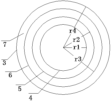
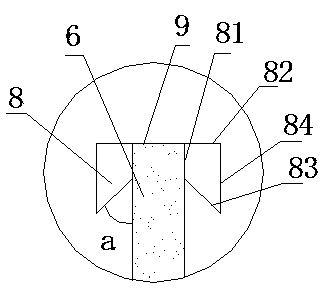
[0011] As shown in the figure, a grinding wheel for high-speed railways includes a grinding wheel base 1 and a grinding wheel main body 2, the grinding wheel main body 2 is fixed above the grinding wheel base 1, and the grinding wheel base 1 includes a base 3 on which the A first baffle plate 4, a second baffle plate 5, a third baffle plate 6 and a fourth baffle plate 7 are provided in the circumferential direction in turn from the inside to the outside. The height of the first baffle plate 4 is H1, and the height of the second baffle plate 5 is H2, the height of the third baffle plate 6 is H3, the height of the fourth baffle plate 7 is H4, the radius of the first baffle plate 4 is r1, the radius of the second baffle plate 5 is r2, and the radius of the third baffle plate 6 is r2. The radius is r3, the radius of the fourth baffle plate 7 is r4, H1=H4


PUM


Abstract

The invention relates to a grinding wheel for a high-speed railway. The grinding wheel comprises a grinding wheel basic body and a grinding wheel main body. The grinding wheel main body is fixed to the position above the grinding wheel basic body, the grinding wheel basic body comprises a base, the base is sequentially provided with a first baffle, a second baffle, a third baffle and a fourth baffle from inside to outside in the circumferential direction, a circle of convex strips are arranged on the outer side of the first baffle in the circumferential direction, the outer side of the second baffle and the inner side of the second baffle are respectively provided with a circle of convex strips in the circumferential direction, the outer side of the third baffle and the inner side of the third baffle are respectively provided with a circle of convex strips in the circumferential direction, and the inner side of the fourth baffle is provided with a circle of convex strips in the circumferential direction. Thus, the grinding wheel basic body and the grinding wheel main body can be firmly fixed to form a whole and are not prone to falling off, the service life is prolonged, and use safety is guaranteed.

Description

technical field [0001] The invention relates to the connection technology of the grinding machine main shaft and the grinding wheel, more specifically, relates to a grinding wheel for high-speed railway. Background technique [0002] During the use of the grinding machine, in order to facilitate the connection between the grinding machine spindle and the resin bonded grinding wheel, to ensure interchangeability and installation connection accuracy, a metal plate is usually added between the above two. It is the base of the grinding wheel, and the base of the grinding wheel provides multiple screw holes with uniform distribution and accurate positions, which can not only be accurately installed and fastened on the main shaft of the grinding machine, but also have a certain effect on improving the strength of the grinding wheel. However, when rough grinding on a vertical grinding machine, the contact surface between the end surface of the grinding wheel and the workpiece is la...

Claims


Application Information

Patent Timeline
Patent Type & Authority Applications(China)
IPC IPC(8): B24D7/00
Inventor 陈启国
Owner 镇江丰成特种工具有限公司
Why Eureka
Try Eureka