
Filtration system for drinking water

A filtration system and drinking water technology, applied in the direction of filtration separation, fixed filter element filter, separation method, etc., can solve the problems of large waste of water resources, reduced service life of filter media, and inability to realize self-purification of separation devices, etc., to achieve Economical and effective use, the effect of improving the service life

Inactive Publication Date: 2014-11-26
杭州恒力机械厂 +1
View PDF6 Cites 0 Cited by
  • Summary
  • Abstract
  • Description
  • Claims
  • Application Information

AI Technical Summary

Problems solved by technology

Increasing the dynamic pressure is limited by the pressure resistance index of the filter medium, and increasing the number of through holes of the filter medium is firstly restricted by the technical conditions of filter medium manufacturing, and secondly, the manufacturing cost will increase significantly; simply increasing the number of filter media will be selected The filter device is bulky and increases the cost. In short, no matter which method is used, it cannot solve the most fundamental problem, that is, the clogging of the filter medium will reduce the service life of the filter medium, especially in the ultra-precision filter system. The problem of service life, although some liquid separation devices have the above-mentioned advantages at present, there are still some disadvantages; the self-purification of the entire separation device cannot be realized, and the interior is generally cleaned after disassembly. Obviously, this method consumes man-hours , In addition, the waste of water resources after washing is relatively large, which is not conducive to environmental protection and rational use of water resources

Method used


Image

  • Filtration system for drinking water

Examples


Embodiment Construction

[0012] The following will clearly and completely describe the technical solutions in the embodiments of the present invention with reference to the accompanying drawings in the embodiments of the present invention. Obviously, the described embodiments are only some, not all, embodiments of the present invention. Based on the embodiments of the present invention, all other embodiments obtained by persons of ordinary skill in the art without creative efforts fall within the protection scope of the present invention.

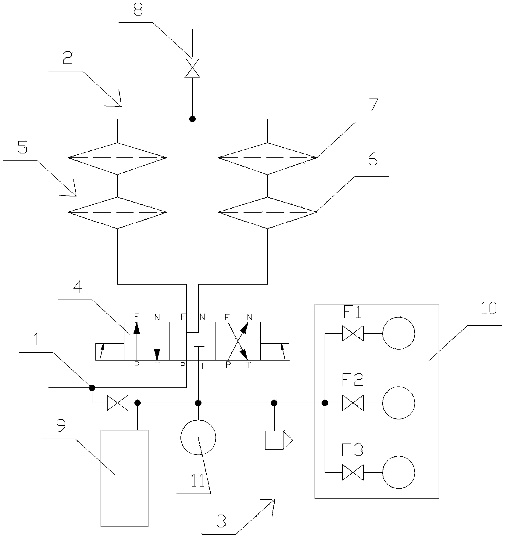
[0013] Such as figure 1 As shown, the drinking water filtration system includes an input end 1, a liquid separation device 2 and a waste water utilization group 3 are connected in parallel on the input end, and the liquid separation device includes a three-position four-way reversing valve 4, a three-position four-way reversing valve The filter unit 5 is connected to the valve, through which high-efficiency and high-density filtration can be achieved, and self-back...


PUM


Abstract

The invention relates to the technical field of environment protection, and relates to a filtration system, particularly a filtration system for drinking water. The filtration system for the drinking water comprises an input end. The input end is provided with a liquid separation device and a wastewater utilization group in parallel. The liquid separation device comprises a three-position four-way directional control valve. The three-position four-way directional control valve is connected to filtration units. The filtration units are provided with two parallel filtration layers through pipes. Output ends of the filtration layers are connected to an outlet valve. The filtration system for the drinking water is advantageous in that during a daily normal water-consuming process, high-frequency automatic backwash on the two groups of the filtration units can be implemented by automatically switching the three-position four-way directional control valve while high-precision filtration on running water is realized, thereby greatly increasing the service life of a filtration medium. Besides, wastewater of the backwash is not discharged without use, and can enter water-consuming points that have low requirements for water quality, such as a water tank of sanitary ware, so as to achieve a water-saving effect that the wastewater is utilized economically and effectively.

Description

technical field [0001] The invention relates to the technical field of environmental protection, and relates to a filtering system, in particular to a drinking water filtering system. Background technique [0002] There are two basic methods of liquid filtration, physical and chemical. The physical method is also called the mechanical method, and it is widely used because of its simplicity and ease of use and relatively low cost of use. The present invention relates only to physical means of filtration. The principle of physical filtration of liquids is very simple, as long as the liquid to be filtered passes through a filter medium (such as filter paper, filter screen, etc.) under a certain pressure, the liquid can be filtered. But this very simple filtration involves two pairs of very prominent contradictions, that is, the contradiction between the precision of the filter medium and the filtration rate (flux); the contradiction between the diameter precision of the filte...

Claims


Application Information

Patent Timeline
IPC IPC(8): B01D35/12B01D29/56B01D29/66
Inventor 邱列扬
Owner 杭州恒力机械厂
Learn More