
A return spring and a static contact device using the return spring

A technology of return spring and static contact, applied in the field of static contact device and return spring, can solve the problems of sudden change of stress of static contact finger and unstable change of force, so as to reduce stress, improve deformation strength and beautiful appearance of products Effect

Active Publication Date: 2017-07-21
STATE GRID CORP OF CHINA +2
View PDF1 Cites 0 Cited by
  • Summary
  • Abstract
  • Description
  • Claims
  • Application Information

AI Technical Summary

Problems solved by technology

[0005] The purpose of the present invention is to provide a return spring to solve the problem that the spring ring in the prior art exerts an unstable force on the static contact finger in the axial direction of the static contact finger, and it is easy to form a sudden change in stress inside the static contact finger. technical problem; at the same time, the present invention also provides a static contact device using the return spring

Method used


Image

  • A return spring and a static contact device using the return spring
  • A return spring and a static contact device using the return spring
  • A return spring and a static contact device using the return spring

Examples


Embodiment Construction

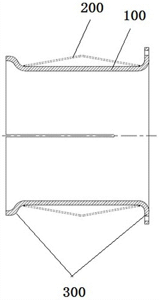
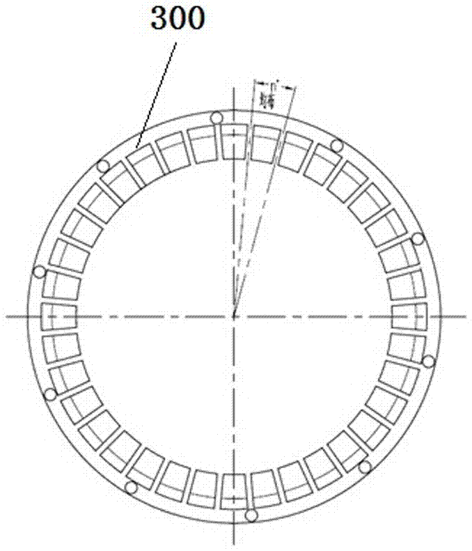
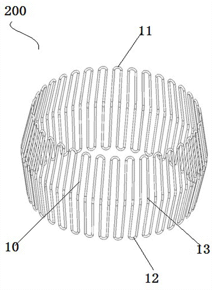
[0025] Such as Figure 1 to Figure 5 As shown, an embodiment of a static contact device, the static contact device in this embodiment includes a static contact body and an elastic static contact finger 100 with one end fixed on the static contact body, the elastic static contact finger 100 A return spring 200 is set on the outer side of the circumferential direction, and the return spring 200 here is a snake-shaped spring sleeve formed by bending and folding a spring wire 10 alternately in forward and reverse directions and welding the end and tail of the spring wire 10. The cross-section is circular, and the wire segment corresponding to the axial end of the serpentine spring sleeve on the spring wire 10 is the first curved segment 11, and the wire segment corresponding to the other axial end of the serpentine spring sleeve is the second curved segment 12. The curved section 11 and the second curved section 12 are U-shaped, and the wire section 13 between the first and second...


PUM


Abstract

The invention discloses a return spring and a static contact device using the return spring. The static contact device includes an elastic static contact finger, and a return spring is arranged on the circumferential outer hoop of the elastic static contact finger. A plurality of spring wires are bent and folded alternately in forward and reverse directions, and the ends of the spring wires are butt-jointed to form a snake-shaped spring sleeve. On the outer peripheral surface of the contact finger corresponding to the axial ends of the snake-shaped spring sleeve, there are respectively stop steps that cooperate with the two ends of the snake-shaped spring sleeve. A deformation gap is formed on the outer peripheral surface of the elastic static contact finger. The force of the serpentine spring sleeve acting on the elastic static contact finger will change uniformly along the axial direction of the serpentine spring sleeve, and the internal stress of the elastic static contact finger will change little, which can effectively prolong the service life of the static contact finger.

Description

technical field [0001] The invention relates to a return spring and a static contact device using the return spring. Background technique [0002] In the field of high-voltage electrical appliances, the electric switch is equipped with corresponding moving contacts and static contacts that are mated and disengaged to control the conduction and disconnection of the switch. The contact finger exerts force to ensure the effective conduction between the static contact and the moving contact. [0003] A Chinese utility model patent with the authorized notification number CN202373467U discloses a static contact device. The static contact device is wrapped by a static contact body, and a spring is provided on the outer peripheral surface of the end of the static contact body facing the moving contact. In the spring groove, there are a plurality of petal-shaped static contact fingers evenly distributed around the spring groove. On the outer peripheral surface of the static contact ...

Claims


Application Information

Patent Timeline
Patent Type & Authority Patents(China)
IPC IPC(8): H01H1/44
Inventor 王路平韩丽娟李宏楼郝留成林生军
Owner STATE GRID CORP OF CHINA
Learn More