Electric bus charging pile safety protection system and its application method in the working process
A technology for electric bus and car charging piles, which is applied in the direction of electric transmission signal systems, illuminated signs, instruments, etc., can solve the problems of inability to prompt information prompts, inability to predict the completion of the charging process from a distance, and inconvenience
- Summary
- Abstract
- Description
- Claims
- Application Information
AI Technical Summary
Problems solved by technology
Method used
Image
Examples
Embodiment 1
[0040] Embodiment 1: as figure 1 and figure 2 As shown, the electric bus charging pile safety protection system described in the present invention includes an electric bus charging bay charging safety protection device, and the electric bus charging bay charging safety protection device is provided with a warning sign 1 and a storage battery 2, and the warning sign 1 There is a warning sign 3 composed of LED lights on the front surface, the battery 2 is connected to the charging power supply, the warning sign 1 is arc-shaped, and the warning sign 1 is equipped with warning signs B4, warning signs C5 and piezoelectric ultrasonic generator on the front surface 6. An alarm circuit 7 is provided on the rear surface of the warning sign 1, and the warning sign 3, the warning sign B4 and the warning sign C5 are connected to the positive and negative poles of the storage battery 2 through the warning circuit 7.
Embodiment 2
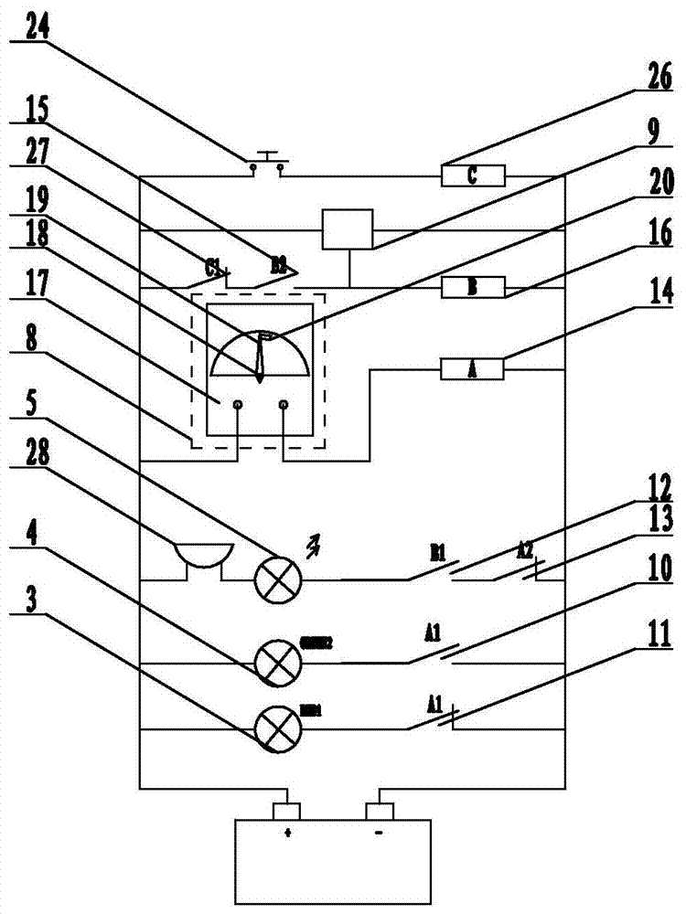
[0041] Embodiment 2: On the basis of the structure described in Embodiment 1, the alarm circuit 7 includes a current detection device 8, a sound wave receiver 9, a relay A, a relay B and an alarm 28, and the warning sign 3 and the warning sign B4 are connected with the relay A respectively. A normally open contact 10 of the relay A and a normally closed contact 11 of the relay A are connected in series on the positive and negative poles of the battery 2, the alarm 28, the warning symbol C5, a normally open contact 12 of the relay B and another normally open contact of the relay A The closed contact 13 is connected in series to form a series circuit 2, the current detection device 8 and the coil 14 of the relay A are connected in series to form a series circuit 3, the other normally open contact 15 of the relay B is connected in series with the coil 16 of the relay B to form a series circuit 4, and the series circuit 2. The two ends of the two power terminals of the series circu...
Embodiment 3
[0042] Embodiment 3: on the basis of the structure described in embodiment 2, as image 3As shown, the current detection device 8 includes an ammeter 17, the ammeter 17 is provided with a metal rotating shaft 18 and a metal pointer 19, the dial is provided with a contact 20, and the ammeter 17 is provided with two signal terminals, one end of which is respectively connected to to the metal rotating shaft 18 and the contact 20, and the other end is respectively connected to the battery 2 and the coil 14 of the relay A. The contact 20 is arc-shaped, and the arc is adapted to the dial. The two ends of the contact 20 correspond to "0A" on the dial respectively. " scale and "5A" scale.
PUM
 Abstract
Description
Claims
Application Information
 - Generate Ideas
- Intellectual Property
- Life Sciences
- Materials
- Tech Scout
- Unparalleled Data Quality
- Higher Quality Content
- 60% Fewer Hallucinations
Browse by: Latest US Patents, China's latest patents, Technical Efficacy Thesaurus, Application Domain, Technology Topic, Popular Technical Reports.
© 2025 PatSnap. All rights reserved.Legal|Privacy policy|Modern Slavery Act Transparency Statement|Sitemap|About US| Contact US: help@patsnap.com


