
Controller capable of automatically adjusting parameters of equipment

A technology for automatic adjustment of equipment parameters, applied in lighting and heating equipment, heating and ventilation control systems, household heating, etc., to solve problems such as large temperature differences, waste of energy, and low room temperature

Inactive Publication Date: 2014-11-19
吴生 +1
View PDF7 Cites 16 Cited by
  • Summary
  • Abstract
  • Description
  • Claims
  • Application Information

AI Technical Summary

Problems solved by technology

[0005] For example 2: If you get up at 7 o'clock on weekdays, you will usually turn off the air conditioner after getting up. There will be two problems: 1) The temperature difference between the inside and outside of the room is very large, and people feel very uncomfortable when leaving the air-conditioned room, and even get sick easily; 2) ) After people get up and leave the air-conditioned room, the temperature in the room is quite low, which wastes a lot of energy;

Method used


Image

  • Controller capable of automatically adjusting parameters of equipment
  • Controller capable of automatically adjusting parameters of equipment
  • Controller capable of automatically adjusting parameters of equipment

Examples


Embodiment 1

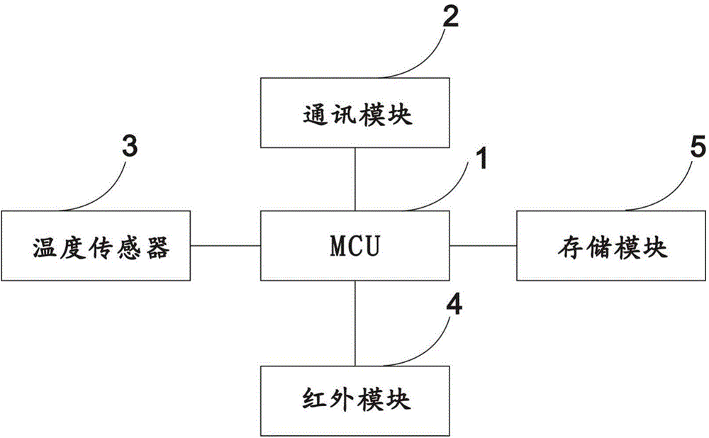
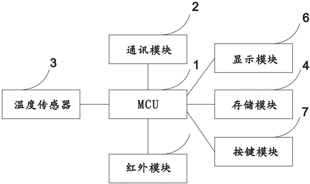
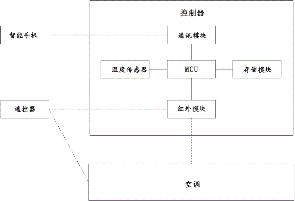
[0030] see figure 1 , a controller for automatically adjusting the temperature of an air conditioner, including a communication module 2, a detection module 3, an infrared module 4, a storage module 5 and an MCU1, wherein the MCU1 is the center, respectively connected to the communication module 2, the detection module 3, the infrared module 4 and the Storage module 5, wherein detection module 3 is temperature sensor 3, and storage module 5 is stored with time and temperature as coordinate axis temperature and the temperature curve corresponding to time, and this temperature curve is sent from the input information component outside air conditioner, and passes The communication module 2 transmits the MCU to the storage module 5 after receiving it. The temperature sensor 3 transmits the temperature value to the MCU1 by sensing the temperature value around the point where the controller is located. The target temperature value automatically calculates the temperature difference...

Embodiment 2

[0040] With reference to embodiment 1, proceed according to the principle of embodiment 1. The difference is that the air conditioner is replaced by a humidifier, the temperature is replaced by humidity, and the temperature sensor is replaced by a humidity sensor.

Embodiment 3

[0042] With reference to embodiment 1, proceed according to the principle of embodiment 1. The difference is that the air conditioner is replaced by an air purifier, the temperature is replaced by an air quality index, and the temperature sensor is replaced by an air quality sensor.


PUM


Abstract

The invention provides a controller capable of automatically adjusting parameters of equipment. The controller comprises a communication module, a detection module, an infrared module, a storage module and an MCU (microprogrammed control unit), the MCU is connected with the communication module, the detection module, the infrared module and the storage module respectively, the detection module is a parameter sensor, the storage module stores parameters taking time and the parameters as coordinate axes and parameter curves corresponding to the time, the parameter curves are transmitted through an input information component out of the equipment and received through the communication module prior to being transmitted to the storage module via the MCU, the parameter sensor senses the parameter values on the periphery of the point where the controller is located and transmits the parameter values to the MCU, and the MCU automatically calculates difference values according to corresponding target parameter values of corresponding time point of the storage module and transmits the difference values to the equipment via the infrared module to perform adjustment. By the controller, the parameters of the equipment can be adjusted in real time so as to meet environmental parameter requirements preset by users, comfort required for a human body can be created, and energy-saving performance of the equipment during use can be improved.

Description

technical field [0001] The invention relates to a controller for automatically adjusting equipment parameters, which can be used for controllers of equipment including air conditioners, humidifiers, air purifiers and the like. Background technique [0002] Take the air conditioner as an example, and use temperature as a parameter to illustrate: [0003] During the whole process of sleep, human body temperature is not balanced, and the requirements for external environment temperature are also inconsistent. In addition, people of different ages have different sleep durations. Young people generally sleep for a long time, and old people sleep for a short time. High-end air conditioners usually work at a constant temperature, which does not conform to human physiological mechanisms and has poor comfort. [0004] Example 1: In summer, the temperature is 31 degrees and you are going to sleep. The temperature of the air conditioner is set to Q1, which is a comfortable temperature...

Claims


Application Information

Patent Timeline
IPC IPC(8): F24F11/00
Inventor 吴生许永贤
Owner 吴生
Learn More