Silo center discharging machine driven by internal motors

A central unloading, motor-driven technology, applied in the direction of conveyor objects, loading/unloading, cleaning devices, etc., can solve problems such as high equipment costs, silo blockage, sticking, knotting, and unloading machine leakage. Achieve effective use of internal space, occupy less space, and reduce equipment costs

Active Publication Date: 2014-11-19
WUXI HUATONG ENVIRONMENTAL PROTECTION EQUIP CO LTD
View PDF7 Cites 6 Cited by
  • Summary
  • Abstract
  • Description
  • Claims
  • Application Information

AI Technical Summary

Problems solved by technology

[0002] At present, in most domestic bulk material industries, such as coal power, grain, cement, paper, etc., silos are used more and more. With the development of silos, the demand for silo unloaders is gradually expanding. However, The discharge equipment at the bottom of the silo is far from keeping up with the speed of silo promotion. In many industries, silos still use the original methods such as gravity self-unloading. In this way, the loose material in the silo has serious problems such as clogging, sticking, and knotting, which is time-consuming and cost-effective. It costs materials and money, and some existing structural equipment have their own advantages and disadvantages. For example, the externally driven unloader has leakage phenomenon, while the cost of the equipment driven by the built-in planetary structure remains high, resulting in the market but An embarrassing situation that is difficult to implement

Method used


Image

  • Silo center discharging machine driven by internal motors
  • Silo center discharging machine driven by internal motors
  • Silo center discharging machine driven by internal motors

Examples


Embodiment Construction

[0014] The present invention will be further described below in conjunction with specific drawings.

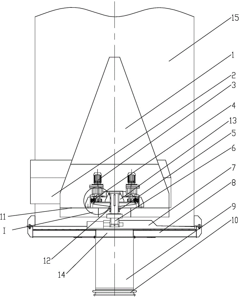
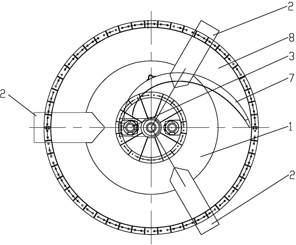
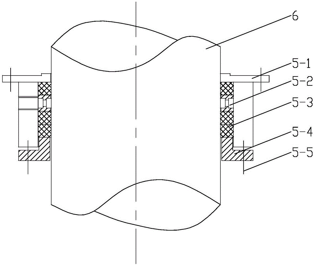
[0015] like Figure 1-Figure 4 As shown: the silo center unloader driven by an internal motor includes a decompression cone 1, a support beam 2, a drive motor 3, a slewing support 4, a shaft seal device 5, a seal seat 5-1, an air ring 5-2, Forming filler 5-3, gland 5-4, compression bolt 5-5, main shaft 6, discharge arm 7, chassis 8, drop pipe 9, compensator 10, bottom plate 11, through hole 12, bushing 13, Outlet 14, silo 15, etc.

[0016] like figure 1 , figure 2 As shown, the present invention includes a decompression cone 1 arranged inside the silo 15. The decompression cone 1 is erected at the bottom center of the silo 15 through a support beam 2. The decompression cone 1 is a hollow structure, and the cone top of the decompression cone 1 Upward, the bottom of the cone is provided with a bottom plate 11, the bottom plate 11 inside the decompression cone 1 is provided ...


PUM


Abstract

The invention relates to a silo center discharging machine driven by internal motors. The silo center discharging machine driven by the internal motors comprises a pressure reduction cone arranged inside a silo, the pressure reduction cone is arranged in the center of the bottom of the silo through a supporting beam in an erecting mode, the driving motors and slewing bearings are arranged on a bottom plate inside the pressure reduction cone, and fixed rings of the slewing bearings are fixed to the bottom plate. A through hole is formed in the center of the bottom plate, a main shaft is arranged in the through hole, the end, stretching into the pressure reduction cone, of the main shaft is sleeved with a shaft sleeve, and the end, stretching out of the pressure reduction cone, of the main shaft is provided with a discharging arm. The shaft sleeve on the main shaft is connected with movable rings of the slewing bearings. A silo bottom flange is connected with a bottom tray, a discharge port is designed in the middle of the bottom tray, and a discharge pipe and compensator are arranged in the discharge port. The silo center discharging machine driven by the internal motors can automatically adjust the discharge speed and meet the discharge requirement for first-in first-out; meanwhile, materials are separated from the driving part and the outside completely, absolute advantages are achieved on the onsite environment and equipment protection, the structure is simplified, and all the requirements for the actions and the stress of the equipment can be achieved with lower cost.

Description

technical field [0001] The invention relates to an unloading machine, in particular to a silo center unloading machine driven by an internal motor, which belongs to the technical field of bulk material loading and unloading equipment. Background technique [0002] At present, in most domestic bulk material industries, such as coal power, grain, cement, paper, etc., silos are used more and more. With the development of silos, the demand for silo unloaders is gradually expanding. However, The discharge equipment at the bottom of the silo is far from keeping up with the speed of silo promotion. In many industries, silos still use the original methods such as gravity self-unloading. In this way, the loose material in the silo has serious problems such as clogging, sticking, and knotting, which is time-consuming and cost-effective. It costs materials and money, and some existing structural equipment have their own advantages and disadvantages. For example, the externally driven u...

Claims


Application Information

Patent Timeline
Patent Type & Authority Applications(China)
IPC IPC(8): B65G65/48B65G45/02B65D88/54
Inventor 孙波张建峰
Owner WUXI HUATONG ENVIRONMENTAL PROTECTION EQUIP CO LTD
Why Eureka
Try Eureka