
Wheel edge motor power coupling transmission system of four-wheel driving vehicle

A wheel-side motor and transmission system technology, applied in the direction of power plant, vehicle components, motion deposition, etc., can solve the problems of large power demand of wheel hub motors, loss of adhesion performance of wheels, idle power of wheel-side motors, etc., to improve power utilization Speed ​​and acceleration performance, eliminating the need for inter-wheel differential locking mechanism, ensuring the effect of movement coordination

Active Publication Date: 2014-11-19
BEIJING INSTITUTE OF TECHNOLOGYGY
View PDF9 Cites 5 Cited by
  • Summary
  • Abstract
  • Description
  • Claims
  • Application Information

AI Technical Summary

Problems solved by technology

However, for off-road vehicles or heavy-duty 4×4 vehicles, the power demand of the hub motor is relatively large, and the existing technical level of the hub motor makes it difficult to control the unsprung quality; therefore, such vehicles usually adopt the scheme driven by the wheel motor
[0004] For 4×4 vehicles driven by wheel motors, in some off-road road conditions, some wheels will lose their adhesion performance in the air. At this time, the load of other wheel motors needs to be increased to obtain sufficient traction, which requires the motor to have good traction. Peak performance; wheel motors that lose adhesion also have the disadvantage of idle power, compared with mechanical four-wheel drive systems, it is difficult to exert full driving force

Method used


Image

  • Wheel edge motor power coupling transmission system of four-wheel driving vehicle
  • Wheel edge motor power coupling transmission system of four-wheel driving vehicle

Examples


Embodiment Construction

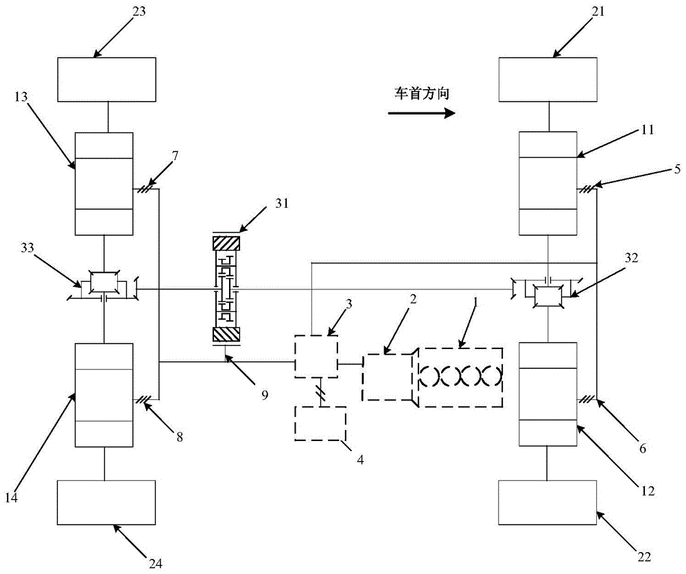
[0020] See attached figure 1 , 4×4 vehicle wheel side motor power coupling transmission system, its specific composition is as follows:

[0021] The front transmission chain part composed of engine 1, generator 2, motor and generator controller 3, and power battery pack 4 can be flexibly placed in the interior space of the vehicle; among them, engine 1 is connected to generator 2, and generator 2 is connected to motor and the generator controller 3 are connected, and the motor and the generator controller 3 are connected with the power battery pack 4;

[0022] The front axle two wheel motors and their reduction gears 11, 12 respectively drive the wheels 21, 22 on both sides of the front axle, and the front axle differential 32 couples the power of the front axle two wheel motors and their reduction gears 11, 12;

[0023] The two wheel side motors of the rear axle and their reduction gears 13, 14 respectively drive the wheels 23, 24 on both sides of the rear axle, and the rear...


PUM


Abstract

The invention belongs to the technical field of power transmission, and particularly relates to a power coupling transmission system. According to the technical scheme of the wheel edge motor power coupling transmission system of a four-wheel driving vehicle, a front transmission chain part is composed of an engine (1), a generator (2), a motor and engine controller (3) and a power battery pack (4); wheel edge motors and speed reducing devices (11, 12, 13 and 14) of the wheel edge motors drive wheels (21, 22, 23 and 24) respectively, a front axle differential mechanism (32) is coupled with the power of the two front axle wheel edge motors and the speed reducing devices (11 and 12) of the two front axle wheel edge motors, and a back axle differential mechanism (33) is coupled with the power of the two back axle wheel edge motors and the speed reducing devices (13 and 14) of the two back axle wheel edge motors; the front axle differential mechanism (32) and the back axle differential mechanism (33) are connected with an electric torque allocating device (31) through a transmission shaft. The electrical power of the wheel edge motors can be reduced, and the power utilization ratio of the motors is improved under the cross-country work condition so as to obtain higher cross-country maneuvering performance.

Description

technical field [0001] The invention belongs to the technical field of power transmission, and in particular relates to a power coupling transmission system. Background technique [0002] 4×4 vehicles usually use components such as transfer case, Torsen differential and limited slip differential to realize power distribution to improve off-road performance and acceleration performance. [0003] With the development of new energy vehicle technology, the distributed drive in the form of in-wheel motors is a current research hotspot. In-wheel motor drive can realize flexible and controllable power distribution between wheels and axles, and realize 4×4 vehicle transmission system and transfer. System functional integration. Each wheel of a small passenger car is driven by an in-wheel motor, and four in-wheel motors share the power demand of the vehicle, which can reduce the power of each in-wheel motor, achieve a small volume and weight, and obtain a reasonable unsprung mass. ...

Claims


Application Information

Patent Timeline
Patent Type & Authority Applications(China)
IPC IPC(8): B60K17/34B60K17/16B60K7/00
Inventor 彭增雄胡纪滨苑士华荆崇波李雪原柳春旺
Owner BEIJING INSTITUTE OF TECHNOLOGYGY
Learn More